Image display method, image display apparatus, and storage medium

Active Publication Date: 2017-07-27
CANON KK
View PDF5 Cites 10 Cited by
  • Summary
  • Abstract
  • Description
  • Claims
  • Application Information

AI Technical Summary

Benefits of technology

[0015]According to this disclosure, understanding of the correspondence between the image relating to the blood fl

Problems solved by technology

However, in the above-mentioned OCTA, a blood flow region can be acquired in detail, and hence an inspector may have difficulty in identifying a connection of a specific vessel of interest and how the specific vessel extends.
However, because the de

Method used


Image

  • Image display method, image display apparatus, and storage medium
  • Image display method, image display apparatus, and storage medium
  • Image display method, image display apparatus, and storage medium

Examples


Example

First Embodiment

[0037]In a first embodiment of this disclosure, an example is described in which a tomographic image is generated from a three-dimensional optical interference signal acquired through imaging, and a motion contrast is calculated to acquire three-dimensional blood flow region information.

[0038][Configuration of Entire Image Forming Apparatus]

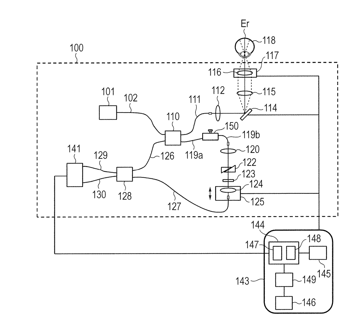
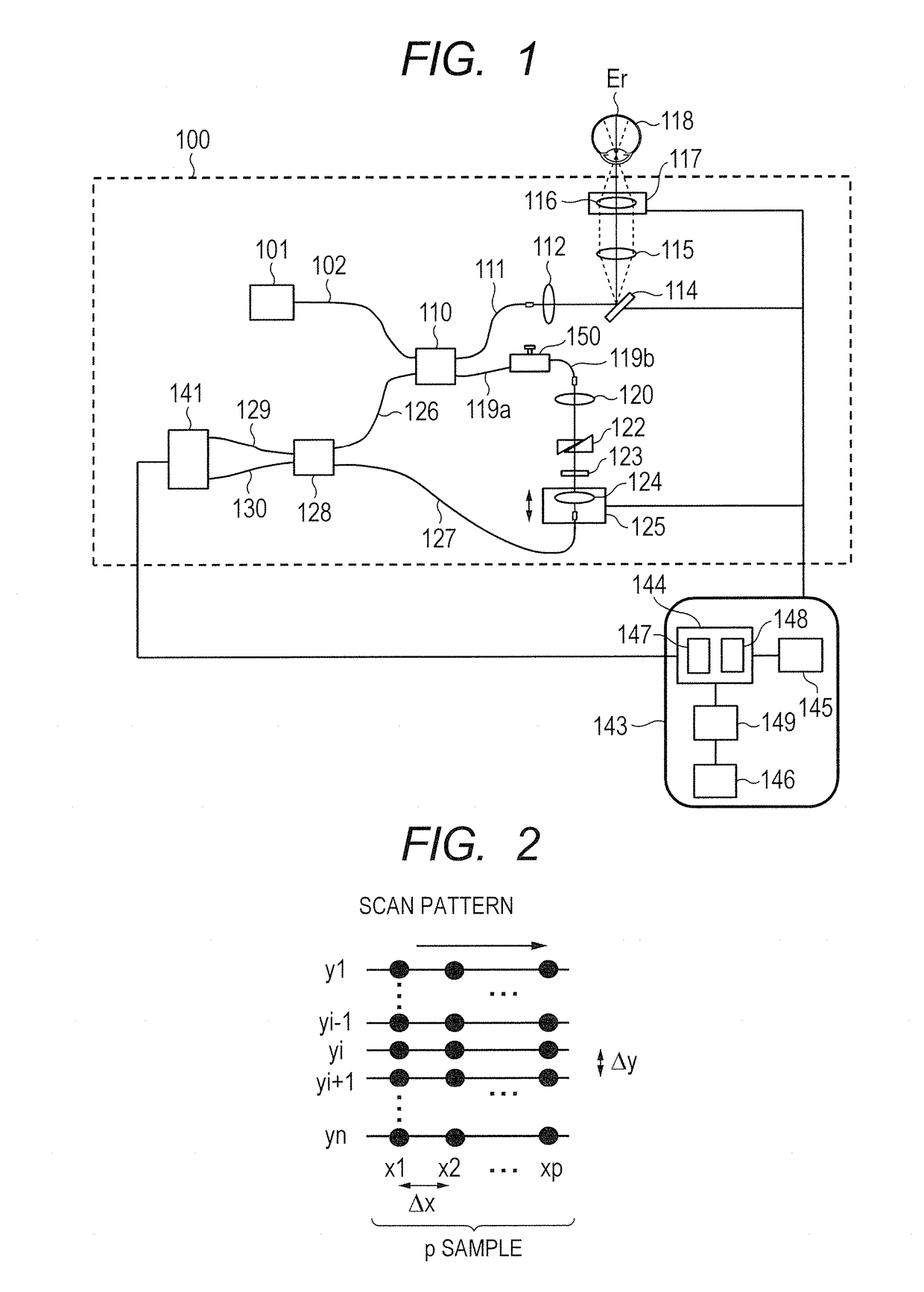
[0039]FIG. 1 is a diagram for illustrating a configuration example of an image forming method and apparatus using optical coherence tomography according to an embodiment of this disclosure. The image forming method and apparatus include an OCT apparatus 100 serving as an optical coherence tomography acquisition unit configured to acquire an optical coherence tomography signal, and a control portion 143. For example, the SD-OCT apparatus and the SS-OCT apparatus described above are applicable to this disclosure as the OCT apparatus. In the embodiment described below, a configuration of a case where the OCT apparatus is the SS-OCT a...

Example

Second Embodiment

[0168]Next, as the second embodiment, a change of the display range in the depth direction is described.

[0169]Through an operation of the slider 405 of FIG. 8, the display ranges to be displayed in the depth direction of the intensity image and the motion contrast image are changed. The slider 405 includes, as described above, the slide portion 405a indicating the depth range to be displayed and the bar 405b indicating the adjustable range of the retina in the depth direction. The slide portion 405a enables a change in the depth direction of a width and position to be displayed as an image, and is used for selecting the display range in the depth direction. In response to the change of the display range through an operation of the slide portion 405a, the intensity image 400 and the motion contrast image 401 to be displayed are updated simultaneously. With the configuration according to this embodiment, the display ranges in the depth direction are changed simultaneo...

Example

Third Embodiment

[0181]Next, a third embodiment of this disclosure is described. In this embodiment, a fundus image is acquired separately from acquisition of the motion contrast image through OCT. The fundus image may be acquired with a fundus camera, a scanning laser ophthalmoscope (SLO), or a vessel image acquired through fluorescence angiography. This configuration forms, as in the configuration for generating the intensity image through OCT according to the first embodiment, an object-to-be-inspected image acquiring unit configured to acquire an object-to-be-inspected image within a first predetermined range of the eye to be inspected 118. As in the intensity image acquired through OCT, a third vessel connection relationship is also calculated from the fundus image acquired through this configuration. The position alignment is performed based on the characteristic amounts of vessels between the calculated vessel connection relationship and the first vessel connection relationshi...


PUM


Abstract

To facilitate understanding of correspondence between a motion contrast image acquired through OCTA and structure information acquired through OCT or the like, when an image is displayed, a first image within a first area of an object to be inspected is acquired, and interference signal sets corresponding to a plurality of frames, which are acquired with an intention to acquire the same cross section, are acquired for a plurality of different cross sections. Then, a motion contrast image within a second area included in the first area is generated based on the interference signal sets corresponding to the plurality of frames, and information acquired from a part of the motion contrast image is superimposed for display onto a corresponding position of the first image.

Description

BACKGROUND[0001]Field[0002]This disclosure relates to an image display method, an image display apparatus, and a storage medium.[0003]Description of the Related Art[0004]As a method of acquiring a tomographic image of an object to be measured, e.g., a living body, in a non-destructive and non-invasive manner, optical coherence tomography (hereinafter referred to as “OCT”) has been put into practical use. OCT is widely used particularly in the field of ophthalmology in order to acquire a tomographic image of a retina in a fundus of an eye to be inspected for ophthalmologic diagnosis of the retina or the like.[0005]In OCT, light reflected from the object to be measured and light reflected from a reference mirror are caused to interfere with each other, and time dependence or wavenumber dependence of an intensity of the interference light is analyzed, to thereby acquire a tomographic image. As apparatus for acquiring such an optical coherence tomographic image, there are known a time d...

Claims


Application Information

Patent Timeline
IPC IPC(8): A61B3/00A61B3/10G02B26/10A61B3/14A61B3/12
CPCA61B3/0058A61B3/14A61B3/1233A61B3/1025A61B3/102A61B3/0025G02B26/101
Inventor SUMIYA, TOSHIHARU
Owner CANON KK
Why Eureka
Try Eureka