
A method for controlling an actuator of a vehicle transmission

a technology of vehicle transmission and actuator, which is applied in the direction of gearing control, gearing elements, belts/chains/gearrings, etc., can solve the problems of reducing the durability of gearbox components, affecting the electronic performance of gearboxes, and ensuring the safety of the transmission system

Active Publication Date: 2017-07-27
VOLVO LASTVAGNAR AB
View PDF0 Cites 4 Cited by
  • Summary
  • Abstract
  • Description
  • Claims
  • Application Information

AI Technical Summary

Benefits of technology

The patent is about controlling gear shifts in transmissions of heavy vehicles like trucks or buses. In some applications, gear shifts are executed when the gears are not synchronized, which can cause noise and dynamic loads. The patent proposes a solution to control non-synchronous gear shifts to achieve lower noise and reduce dynamic loads. This solution is cost-effective as it requires less components and has lower weight.

Problems solved by technology

However, this method for shifting gear is often associated with the provision of high dynamic loads and unwanted noise when the engaging sleeve hits the gear to be engaged in the axial direction thereof.
The dynamic loads may, if they are too severe, result in a reduction of gearbox component durability, as well as to negatively affect gearbox electronics due to shock loads resulting from the dynamic loads.
However, if the teeth of the engaging sleeve will, for example, hit the teeth of the gear wheel to be engaged during the predetermined second time period, the forces on the engaging sleeve directing the engaging sleeve towards the engaging position will eventually be reduced to limits that will not be able to fully engage the engaging sleeve when the teeth of the engaging sleeve is no longer in connection with the teeth of the gear wheel.

Method used


Image

  • A method for controlling an actuator of a vehicle transmission
  • A method for controlling an actuator of a vehicle transmission
  • A method for controlling an actuator of a vehicle transmission

Examples


Embodiment Construction

[0037]The present invention will now be described more fully hereinafter with reference to the accompanying drawings, in which exemplary embodiments of the invention are shown. The invention may, however, be embodied in many different forms and should not be construed as limited to the embodiments set forth herein; rather, these embodiments are provided for thoroughness and completeness. Like reference character refer to like elements throughout the description.

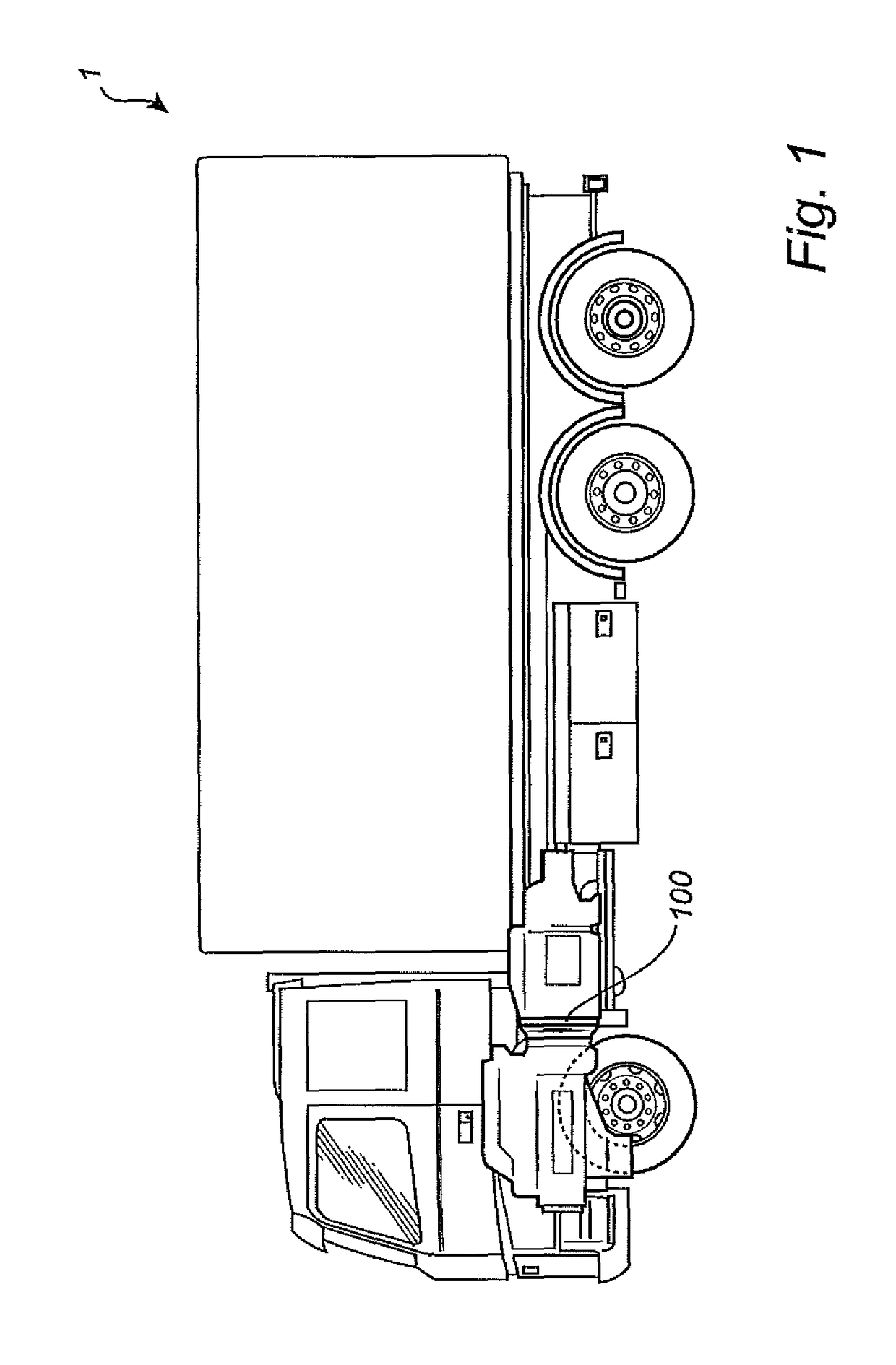
[0038]With particular reference to FIG. 1, there is provided a vehicle 1 with a transmission 100 according to the present invention. The vehicle 1 depicted in FIG. 1 is a truck for which the inventive transmission and associated method for controlling the actuator, as will be described further below, is particularly suitable for.

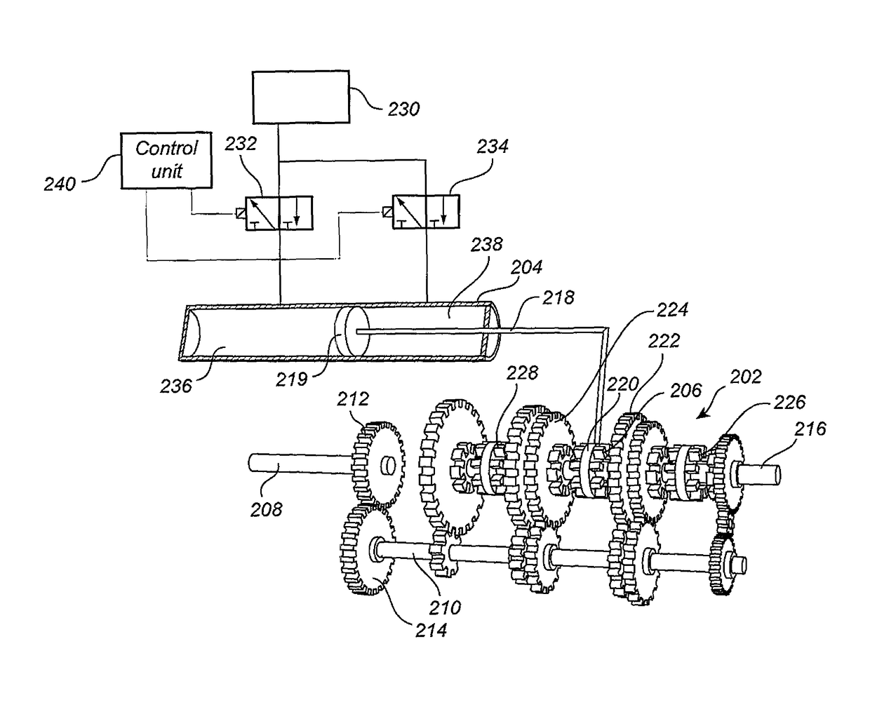
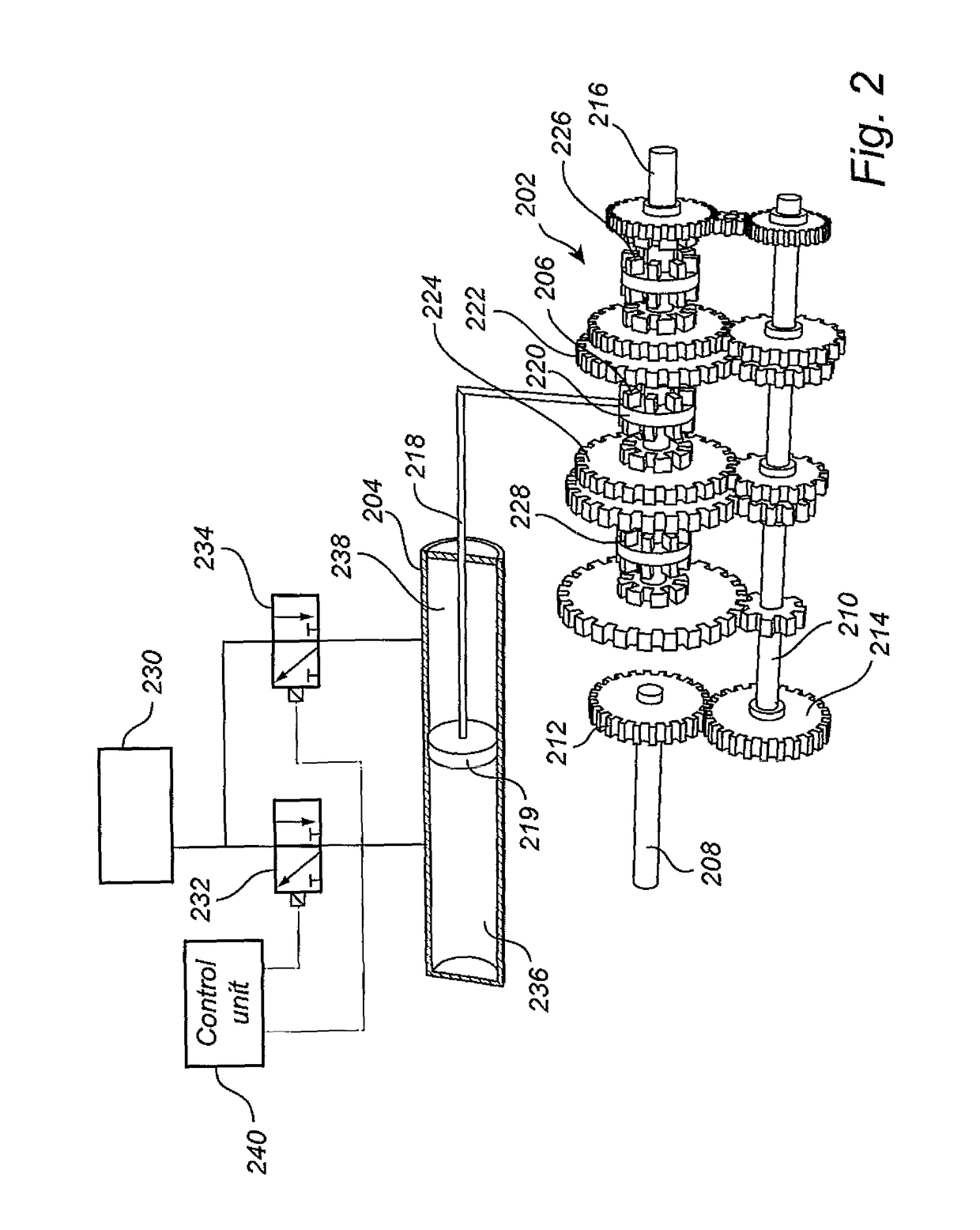
[0039]Turning to FIG. 2, there is illustrated a portion of a vehicle transmission 202 which is connected to an actuator 204 for controlling an engaging sleeve 206. The actuator 204 is illustrated in a...


PUM


Abstract

A method is provided for controlling an actuator of a vehicle transmission, the actuator being connected to an engaging sleeve, the engaging sleeve being axially displaceable between a gear wheel disengaging position and a gear wheel engaging position of the vehicle transmission for executing a transmission gear shift. The method includes actuating the actuator during a first predetermined time period for initiating a translational movement of the engaging sleeve front the gear wheel disengaging position towards the gear wheel engaging position, wherein the first predetermined time period is smaller than a total time period for the engaging sleeve to reach the gear wheel engaging position, determining, during a second predetermined time period initiated after the duration of the first predetermined time period, if the engaging sleeve has reached the gear wheel engaging position, and actuating the actuator during a third predetermined time period if it was determined that the engaging sleeve failed to reach the gear wheel engaging position during the second predetermined time period. A corresponding computer, computer readable medium, control unit, and vehicle transmission are also provided.

Description

BACKGROUND AND SUMMARY[0001]The present invention relates to a method for controlling an actuator of a vehicle transmission. The invention also relates to a corresponding computer program, computer readable medium, control unit, and vehicle transmission. The invention is applicable on vehicles, in particularly heavy duty vehicles such as e.g. trucks or working machines. However, although the invention will mainly be described in relation to a truck, the invention is of course also applicable for other type of vehicles, such as e.g. cars or buses. etc.[0002]In relation to vehicle transmissions, for example, transmissions used in heavy duty vehicles such as trucks or buses etc., an automated manual transmission is often utilized. The automated manual transmission changes gear automatically such that gear and specific time of changing gear is executed automatically. It is common and well known to execute a gear shift when the gears are synchronized, i.e. the relative speed between the ...

Claims


Application Information

Patent Timeline
Patent Type & Authority Applications(United States)
IPC IPC(8): F16H61/12F16H63/30
CPCF16H61/12F16H2063/3093F16H63/3023F16H2061/2823F16H2061/0474F16H61/30
Inventor LYGNER, OSKARKARPENMAN, FREDRIK
Owner VOLVO LASTVAGNAR AB
Learn More