
Container, method for obtaining same and target assembly for the production of radioisotopes using such a container

Active Publication Date: 2017-07-27
NANOMARKER SPRL
View PDF6 Cites 4 Cited by
  • Summary
  • Abstract
  • Description
  • Claims
  • Application Information

AI Technical Summary

Benefits of technology

The invention is a container that is easy to use, does not require assembling, and can be quickly detached and remounted. It has a thin window that allows for easy targeting and can also act as a beam stop during set-up of an accelerator. The container is cost-effective and waste-minimal. The technical effects of this invention are improved efficiency and ease of use for targeting and beam stopping in medical and scientific settings.

Problems solved by technology

However, it requires that the beam be extracted from the accelerator, this presenting many difficulties.
The various known extracting means, such as stripping, electrostatic or magnetic deflection and self-extraction each also has known difficulties.
Extraction by stripping is relatively easy, but requires negative ions that are less stable during the acceleration, more difficult to produce and that require a higher vacuum.
When the successive turns are closely spaced or overlap, a fraction of the beam strikes the septum, which heats up, is activated and may be damaged.
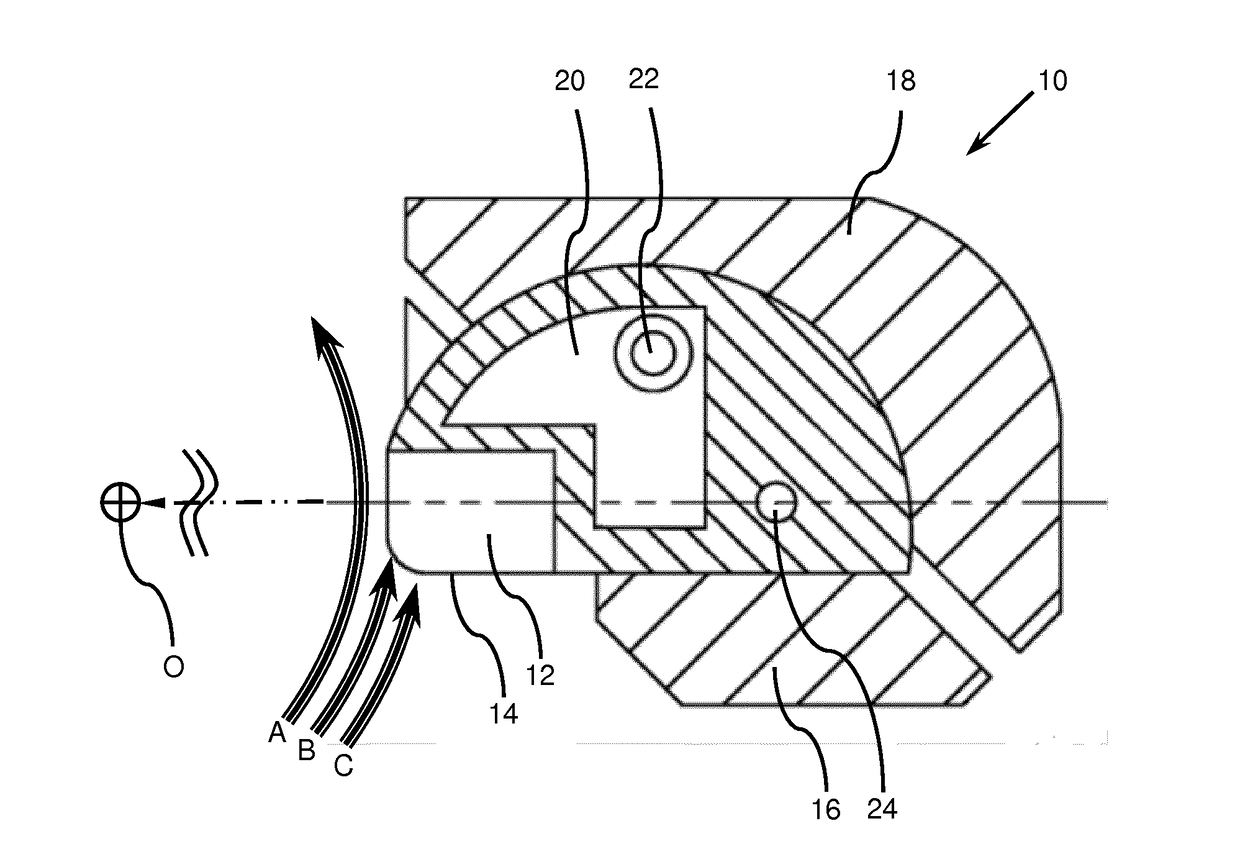
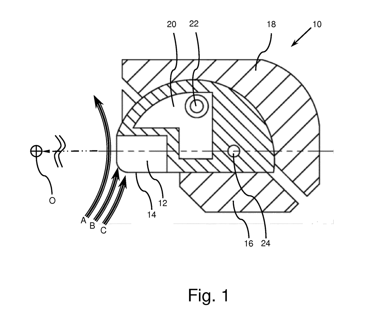
Some of this beam does not interact with the precursor contained in the chamber, but with the covering sheet 14, thus losing its energy without producing a useful effect.
This implies a precise and therefore difficultly reproducible adjustment of the orientation of the target during each intervention.
The assemblage of this target, in particular of the covering sheet, is tricky and the resulting assembly is fragile.
However, the thickness required to allow the two tubes and two hemispheres to be welded and formed means that the beam loses a significant portion of its energy as it passes therethrough, this producing heat, and meaning that additional cooling of the zone of penetration of the beam is required.
This additional cooling is achieved by a flow of water and hence the aluminum window and the layer of water are required, which in turn cause a loss of energy and the production of heat.
Because of the need for additional cooling, this target is not suitable for use as an internal target.

Method used


Image

  • Container, method for obtaining same and target assembly for the production of radioisotopes using such a container
  • Container, method for obtaining same and target assembly for the production of radioisotopes using such a container
  • Container, method for obtaining same and target assembly for the production of radioisotopes using such a container

Examples


Embodiment Construction

[0037]FIG. 1 is a cross-sectional view of a prior-art container, namely that of WO2013049809, and was described above.

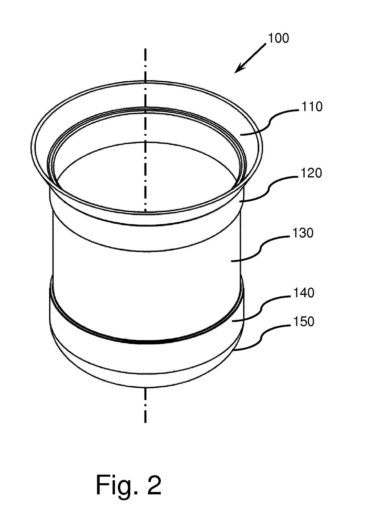
[0038]FIG. 2 is a semi-isometric perspective view of a container 100 according to the invention. This container 100 takes the form of a “thimble”, having a symmetry of revolution about an axis. The upper portion 110 is open and may have a conical shape, the opening of the cone being oriented upward. As explained below, this arrangement is of benefit as regards the assemblage of the container 100 into a target assembly. The top of a first cylindrical portion 120 is connected to the upper portion 110 and its bottom is connected to a thin wall section 130. This thin wall section 130 is connected to a second cylindrical portion 140, that itself is connected to a dome 150 closing the container 100 at the bottom. The thickness of the thin fraction is smaller than or equal to 100 μm and for example 80, 60, 40, 20, 10 or even 5 μm. A smaller thickness gives a better transpar...


PUM

PropertyMeasurementUnit
Lengthaaaaaaaaaa
Lengthaaaaaaaaaa
Thicknessaaaaaaaaaa

Abstract

The invention relates to a container (100, 901, 902, 903, 904, 905, 906, 907, 908, 909, 910) for the production of radioisotopes by irradation of a precursor material formed by a one-piece metal casing, the wall of said casing including one thin portion (130) having a thickness of between 5 and 100 μm, the remainder having a thickness greater than 100 μm. The invention also relates to a method for obtaining the container and to a target assembly using same.

Description

TECHNICAL FIELD[0001]The invention relates to a container usable for producing radioisotopes, to a method allowing such a container to be obtained, and to a target assembly including such a container.DESCRIPTION OF THE PRIOR ART[0002]It is known to produce a radioisotope by irradiating a target containing a precursor of the radioisotope by means of a beam of particles. In particular, 18F is produced by irradiating a target material containing 18O-enriched water with a beam of protons.[0003]A particle accelerator, such as a cyclotron or a linac, is used to produce the beam of particles. When the precursor of the radioisotope is a liquid or a gas, the target includes a container including a chamber or cavity that is generally closed by a window that allows the beam to pass without being weakened substantially. This window must therefore be as thin as possible, but must withstand the mechanical and thermal stresses and the radiation to which it is subjected in operation. The power diss...

Claims


Application Information

Patent Timeline
IPC IPC(8): G21K5/08H05H13/00C25D1/00G21G1/10
CPCG21K5/08G21G1/10G21G2001/0015C25D1/003H05H13/005H05H6/00
Inventor CONARD, MILO
Owner NANOMARKER SPRL
Learn More