Rotary Electric Machine Housing and Rotary Electric Machine Equipped Therewith

a technology housings, which is applied in the direction of propulsion parts, propulsion using engine-driven generators, transportation and packaging, etc., can solve the problems of increasing the distance between press fittings, reducing production efficiency and upsizing shrink fitting equipment, and the structure of rotary electric machines is larger. , to achieve the effect of reducing the force of press fittings and high cooling

Active Publication Date: 2017-08-03
HITACHI ASTEMO LTD
View PDF2 Cites 13 Cited by
  • Summary
  • Abstract
  • Description
  • Claims
  • Application Information

AI Technical Summary

Benefits of technology

[0016]The first aspect of the present invention can provide a rotary electric machine housing, as well as a rotary electric machine equipped with the same, in which the housing allows the reduction of press fitting force required in each of two press fitting steps and has a high cooling effect.
[0017]Problems, configurations and effects other than those described above will be made clear by

Problems solved by technology

However, increasing the thickness of the laminated stator will make the rotary electric machine structure larger.
This disadvantage has generated concerns about reduced production efficiency and upsized shrink fitting equipment.
A thicker laminated stator also causes an increase in press fitting distance.
This increases required press fitting force and necessitates upsizing of press fitting equipment.

Method used


Image

  • Rotary Electric Machine Housing and Rotary Electric Machine Equipped Therewith
  • Rotary Electric Machine Housing and Rotary Electric Machine Equipped Therewith
  • Rotary Electric Machine Housing and Rotary Electric Machine Equipped Therewith

Examples


example 1

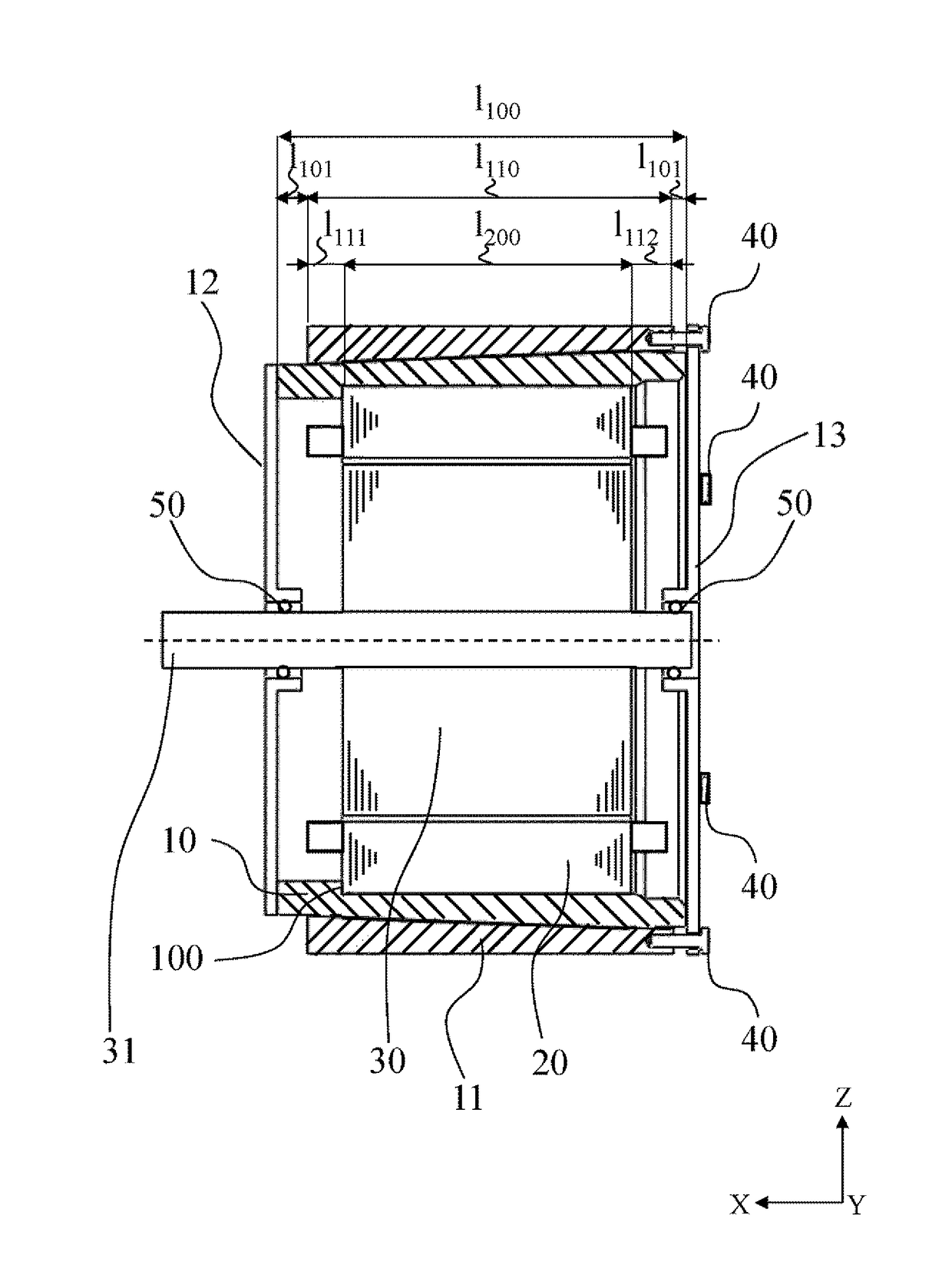
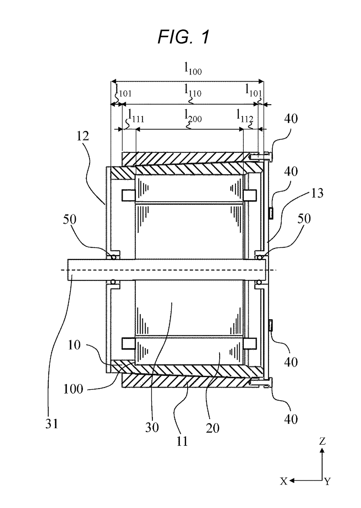
[0032]With reference to FIGS. 1 to 7, a first embodiment will now be described.

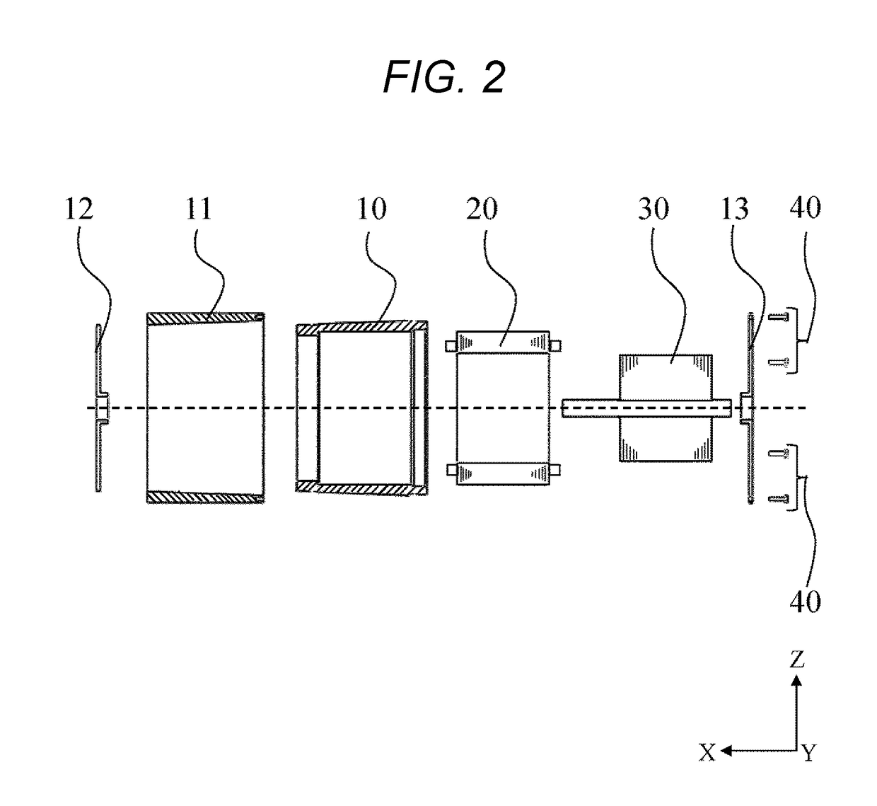
[0033]A rotary electric machine according to the first embodiment includes an internal housing cylinder 10, an external housing cylinder 11 fastened to the outer perimeter of the internal housing cylinder 10 concentrically by press fitting, and a front housing 12 and a rear housing 13 for closing the openings of the internal housing cylinder 10. The front and rear housings 12 and 13 are fastened to the internal housing cylinder 10 by shrink or press fitting, bolts, bonding, welding, caulking, rivets or any other method.

[0034]The front housing 12 may be integrated with the internal housing cylinder 10 by die casting or any other casting.

[0035]The housing cylinder 11 has a stator 20 along its inner diameter end. The position of the stator 20 is determined in the axial direction by putting the stator 20 into contact with a stopper 100 provided on the internal housing cylinder 10. The stator 20 has a rotor 30...

example 2

[0047]With reference to FIGS. 8 to 11, a second embodiment will now be described. As for structural elements identical to those of the first embodiment, redundant description thereof is omitted.

[0048]In this embodiment, an internal housing cylinder 10 includes circumferential coolant ducts 151, 152, and 153 being incurved on part of its tapered outer face toward the inner diameter end, and duct walls 141, 142, 143, and 144 on its outer diameter face. A tapered external housing cylinder 11 is fastened to the duct walls 141, 142, 143, and 144 so as to partially create contact surface pressure, i.e. position fixing force, between a stator 20 and the internal housing cylinder 10.

[0049]The circumferential ducts 151, 152, and 153 are formed like three swathes along the outer perimeter of the stator 20. The circumferential ducts 151 and 152 are connected to each other via a joint duct 161 in the axial direction, while the circumferential ducts 152 and 153 are connected to each other via a ...

example 3

[0056]With reference to FIGS. 3 and 12, a third embodiment will now be described. As for structural elements identical to those of the first embodiment, redundant description thereof is omitted.

[0057]In this embodiment, widths l142 and l143 of duct walls 142 and 143 are made larger than widths l141 and l144 of duct walls 141 and 144. An interference of the duct walls 142 and 143 to an external housing cylinder 11 is made larger than an interference of the duct walls 141 and 144 to the external housing cylinder 11. Press fitting of the tapered duct walls 142 and 143 mostly creates a contact surface pressure required for securing a stator 20 to a housing 10. Particularly, the largest stress is put on an outer diameter site of the external housing cylinder 11 that is located circumferentially over a rear housing 13 side of the duct wall 144. The thickness of an external cylinder section on the outer perimeter of the duct walls 142 and 143 is larger than that of an external cylinder sec...


PUM


Abstract

Provided is a rotary electric machine housing and a rotary electric machine equipped with the same. The housing allows the reduction of press fitting force required in each of two press fitting steps and has a high cooling effect. This rotary electric machine housing includes an internal cylinder 10 allowing press fitting of a stator 20 along an inner diameter end of the internal cylinder. The internal cylinder 10 has an internal cylinder-side tapered face on its outer diameter end surface. The housing further includes an external cylinder 11 having an external cylinder-side tapered face on an inner diameter end of the external cylinder. The external cylinder-side tapered face fits onto the internal cylinder-side tapered face. It is preferred that an inner diameter of the internal cylinder be smaller than an outer diameter of the stator; an outer diameter of the internal cylinder be larger than an inner diameter of the external cylinder; and a difference between the outer diameter of the internal cylinder and the inner diameter of the external cylinder be larger than a difference between the inner diameter of the internal cylinder and the outer diameter of the stator.

Description

TECHNICAL FIELD[0001]The present invention relates to a rotary electric machine housing and a rotary electric machine equipped with the same.BACKGROUND ART[0002]Rotary electric machines are used, for example, in auxiliary motors for internal combustion engines for driving hybrid electric vehicles (HEVs) and in main motors for driving electric vehicles (EVs).[0003]Housings for these rotary electric machines are required to prevent the stator from being slipped by torque reaction or inertial force owing to vibrations acting on the stator and to dissipate or transfer heat generated at the stator conductor to outside the machine or the coolant.[0004]It is known that a conventional rotary electric machine housing has a structure made up of a substantially cylindrical center housing, as well as a front housing and a rear housing for closing the openings of the center housing. A known rotary electric machine having this housing structure includes a center housing, and front and rear housin...

Claims


Application Information

Patent Timeline
Patent Type & Authority Applications(United States)
IPC IPC(8): B60K6/405B60K6/26
CPCB60K6/405B60L11/14B60W10/08B60K6/26H02K5/04H02K1/185B60L50/16H02K5/203
Inventor NAGAO, RIICHIYAMAZAKI, SHINJI
Owner HITACHI ASTEMO LTD
Why Eureka
Try Eureka