Hybrid power source and control moment gyroscope

a technology of control moment and power source, which is applied in the field of self-guided aerial vehicles, can solve the problems of physical limitation of the amount of payload that a respective vehicle is capable of carrying, the inability to carry a specific amount of payload, and the inability to provide the necessary power supply

Active Publication Date: 2017-08-03
THE BOEING CO
View PDF1 Cites 14 Cited by
  • Summary
  • Abstract
  • Description
  • Claims
  • Application Information

AI Technical Summary

Benefits of technology

[0008]As an example of operation, the HPCMG performs a method that provides spatial stability and electrical power to a vehicle with the HPCMG. The method includes spinning a central mass within a first transverse gimbal assembly along a first axis of rotation of the CMG, producing spatial stability force for the HPCMG as a result of spinning the central mass, producing a voltage potential with the central mass, and discharging the central mass through two conductive bearings.

Problems solved by technology

While CMGs are very useful for both attitude control and inertial navigation systems of these types of vehicles, their disadvantage is weight that induces a weight penalty on the respective vehicle.
Additionally, the necessary power supplies of these vehicles are also heavy components because they typically include electrical batteries that are heavy devices.
As a result, vehicles in the aerospace, submersible, space-access, and space-based areas have a problem that the physical limitation on the amount of payload that a respective vehicle is capable of carrying is directly related to the combined weight of all the on-board components and devices on that vehicle.
This problem increases as these vehicles become smaller, carry more payload, or both.

Method used


Image

  • Hybrid power source and control moment gyroscope
  • Hybrid power source and control moment gyroscope
  • Hybrid power source and control moment gyroscope

Examples


Embodiment Construction

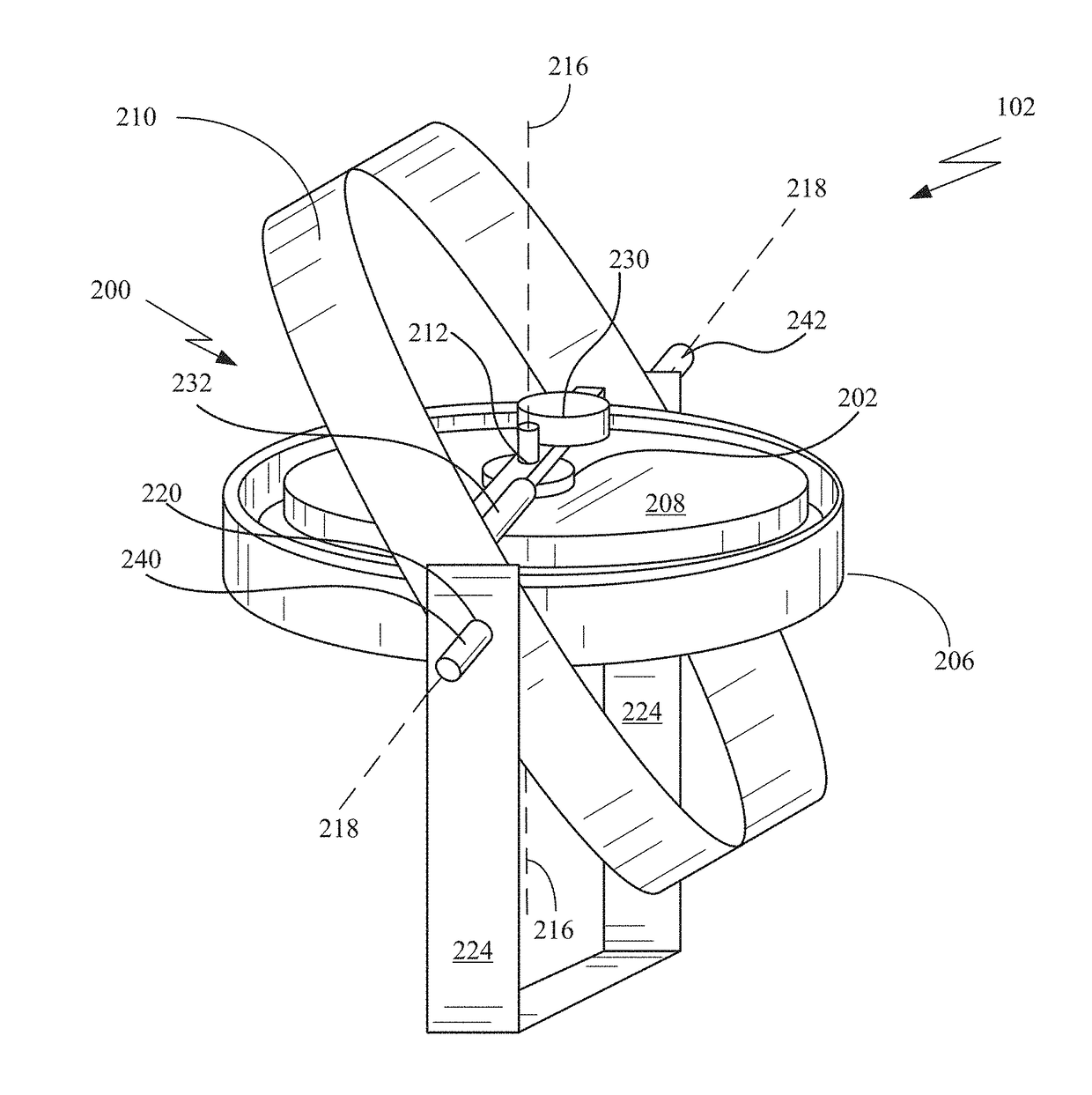
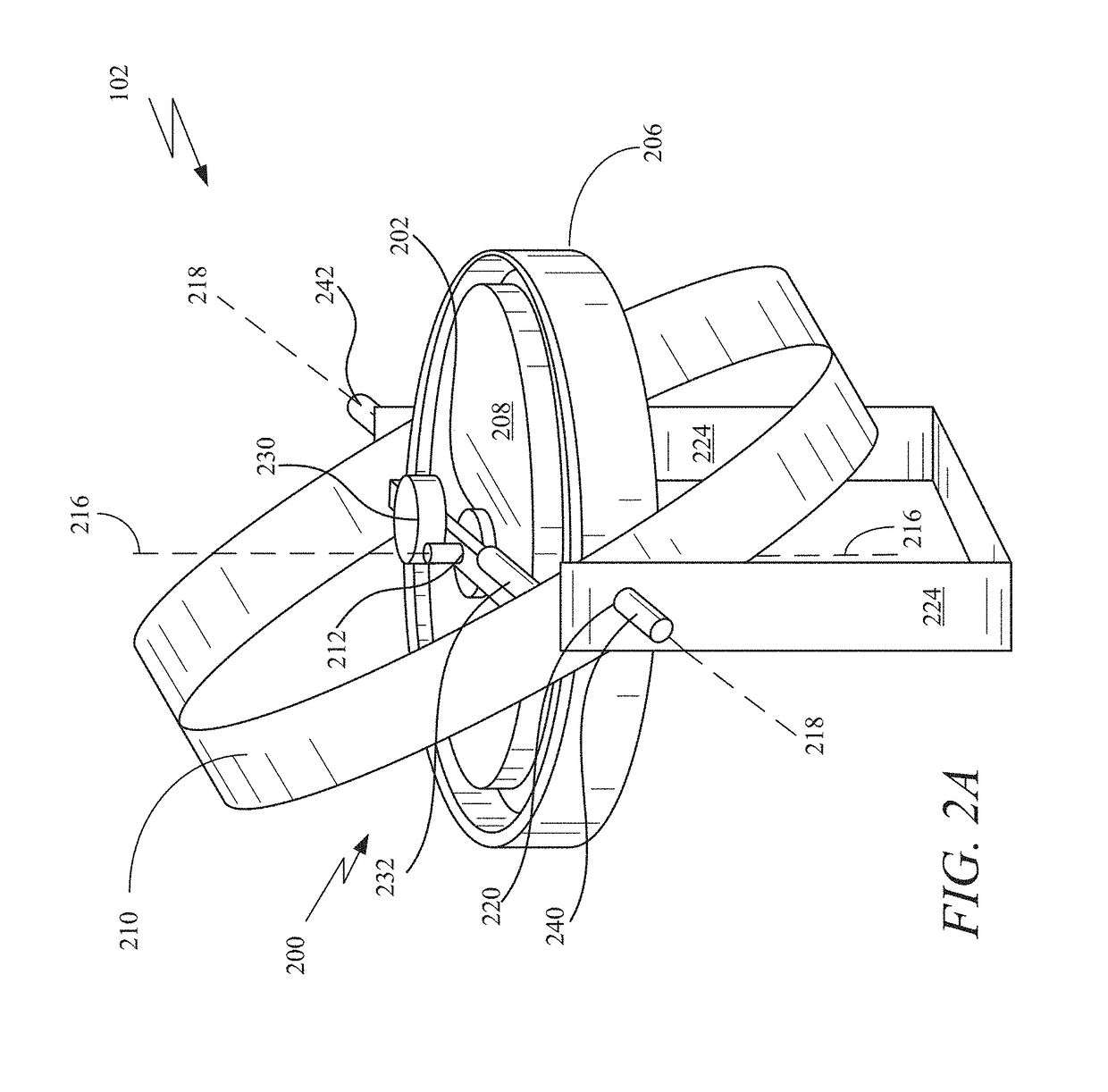
[0020]A hybrid power source and control moment gyroscope (“HPCMG”) is disclosed. The HPCMG includes a control moment gyroscope (“CMG”), a first conductive bearing, and a second conductive bearing. The CMG includes a first transverse gimbal assembly, a central mass that produces a voltage potential, and a second gimbal assembly rotationally connected to the first transverse gimbal assembly. The first transverse gimbal assembly is rotationally connected to the central mass at a first position of the transverse gimbal assembly and a second position of the transverse gimbal assembly along a first axis of rotation and the central mass is configured to spin about the first axis of rotation and the first transverse gimbal assembly is configured to rotate about a second axis of rotation at a first position of the second gimbal assembly. The first conductive bearing rotationally connects the central mass with the first position of the first transverse gimbal assembly along the first axis of ...


PUM


Abstract

A hybrid power source and control moment gyroscope (“HPCMG”) is disclosed. The HPCMG includes a control moment gyroscope (“CMG”), a first conductive bearing, and a second conductive bearing. The CMG includes a first transverse gimbal assembly, a central mass that produces a voltage potential, and a second gimbal assembly rotationally connected to the first transverse gimbal assembly. The first transverse gimbal assembly is rotationally connected to the central mass along a first axis of rotation and the central mass is configured to spin about the first axis of rotation and the first transverse gimbal assembly is configured to rotate about a second axis of rotation of the second gimbal assembly. The first conductive bearing rotationally connects the central mass with the first position of the first transverse gimbal assembly along the first axis of rotation.

Description

BACKGROUND[0001]1. Field[0002]The present invention relates to self-guided aerial vehicles, and more, particularly to control moment gyroscopes (“CMG”).[0003]2. Related Art[0004]At present a number of vehicles (such as, for example aircraft, spacecraft, and surface and submersible marine vehicles) utilize control moment gyroscopes (“CMG”) as attitude control devices within attitude control and inertial navigation systems of the vehicles. In general, a CMG is a device that includes a gyroscope that includes a spinning rotor and one or more motorized gimbals that tilt the angular momentum of the rotor. As is appreciated by those of ordinary skill in art, a gyroscope is a device that includes the spinning rotor where the axis of rotation of the spinning rotor is free to assume any orientation and the orientation of this axis of rotation is unaffected by tilting or rotation of the gimbal because of the conservation of angular momentum. Additionally, a gimbal is a pivoted support structu...

Claims


Application Information

Patent Timeline
Patent Type & Authority Applications(United States)
IPC IPC(8): G01C19/10B64C17/06B63B39/04B63G8/14G05D1/08B64G1/28
CPCG05D1/08B64G1/285G01C19/10B63G8/14B64C17/06B63B39/04B64G1/286B64G1/421B64G1/425
Inventor VETO, CHRISTOPHER C.
Owner THE BOEING CO
Why Eureka
Try Eureka