
Single Phase Motor and Rotor of the Same

a single-phase motor and rotor technology, applied in the field of single-phase motors, can solve problems such as instability of the achieve the effects of stable starting position of the motor, good starting reliability and small starting curren

Inactive Publication Date: 2017-08-03
JOHNSON ELECTRIC SA
View PDF3 Cites 0 Cited by
  • Summary
  • Abstract
  • Description
  • Claims
  • Application Information

AI Technical Summary

Benefits of technology

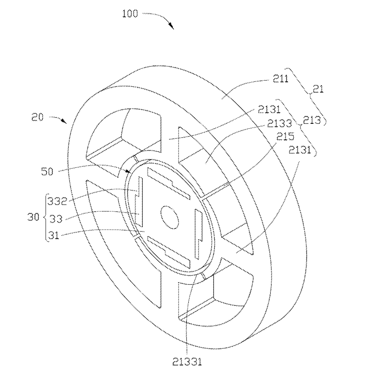
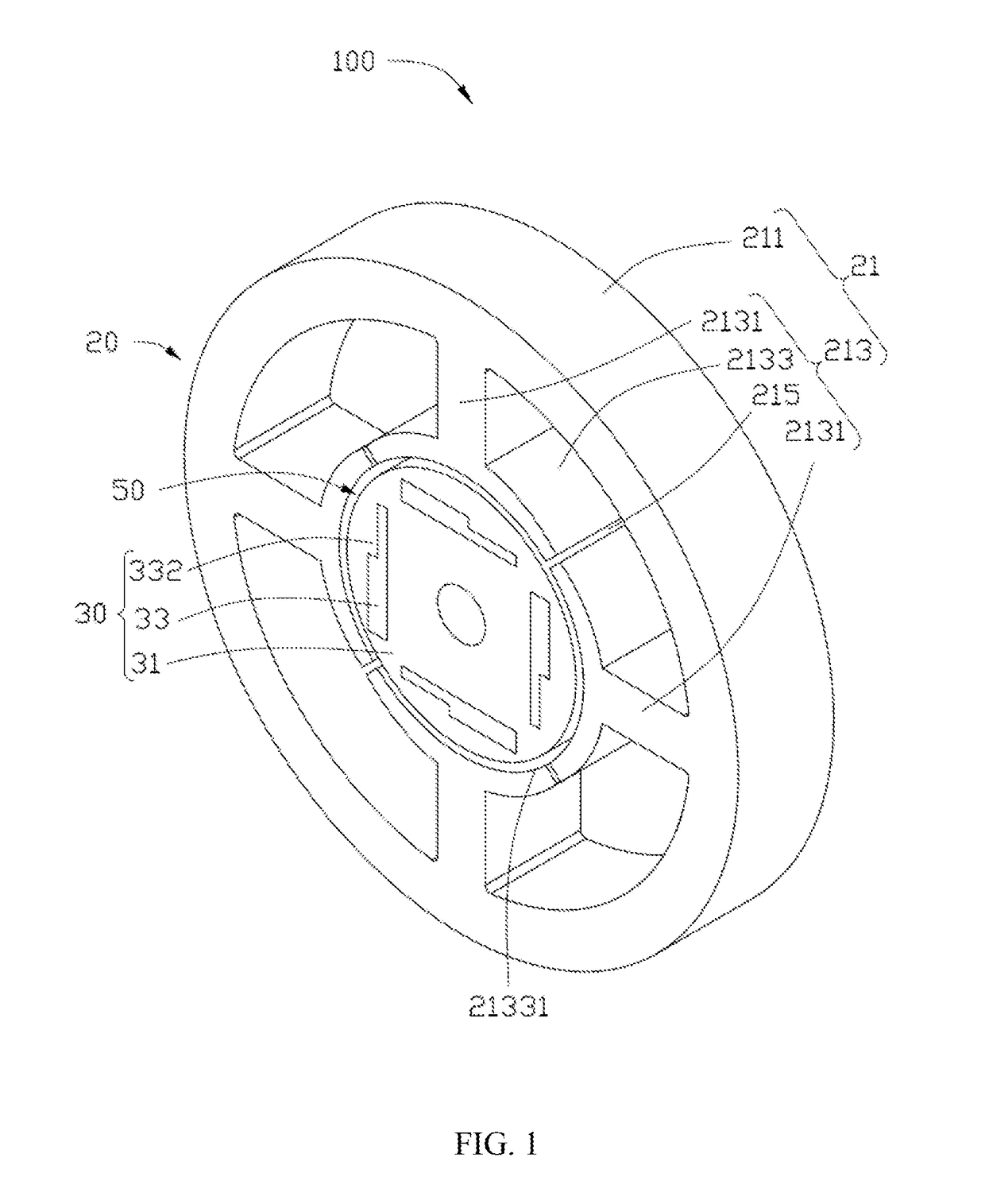
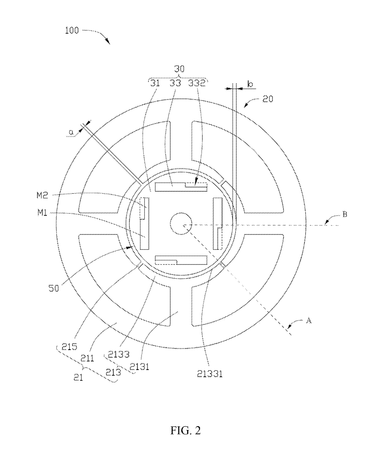
The present disclosure provides a new type of single phase motor rotor that improves starting reliability. The rotor has an asymmetric structure with a notch at one end, which results in uneven reluctance between the permanent magnet and stator pole. This avoids the starting dead point of the motor, making the start-up more stable. The starting current is small, further improving the starting reliability.

Problems solved by technology

However, the existence of the slots increase the magnetic resistance between the part of the stator core where the slot is defined and the rotor permanent magnet, the stator core has starting dead point.
At this point, the rotor is subjected to zero torque, resulting in motor starting instability.

Method used


Image

  • Single Phase Motor and Rotor of the Same
  • Single Phase Motor and Rotor of the Same
  • Single Phase Motor and Rotor of the Same

Examples


Embodiment Construction

[0027]More clear and complete descriptions concerning the technical solution of the embodiments of the present invention will now be made with reference to the accompanying drawings of the embodiments of the present disclosure, obviously, the embodiments described hereof are just a partial embodiments of the present invention, rather than all embodiments of the present invention. All other embodiments obtained by those ordinary technicians in the art based on the embodiments of the present invention under the premise of making no contribution of creative work shall belong to the scope of the protection of the present invention.

[0028]It's important to note that when a component is referred to as being “fixed” to another component, it may be fixed directly on another component or there may be an intermediate component as well. When a component is identified as being “connected” to another component, it may be directly connected to another component or there may be an intermediate comp...


PUM


Abstract

A single phase motor includes a stator and a rotor. The stator includes a stator core. The stator core includes an outer yoke and a plurality of stator teeth. Each stator tooth includes a winding portion and a pole shoe coupled to the winding portion. The rotor includes a rotor core and a plurality of permanent magnets. The permanent magnets are embedded in the rotor core and evenly distributed in the circumferential direction of the rotor core. Each permanent magnet has a stripe-shaped asymmetric structure, and cross-sectional areas at both ends of each permanent magnet are not equal. The initial position of the rotor is able to avoid the dead point position, and the start-up of the motor is stable. The present invention also provides a rotor for the single phase motor.

Description

CROSS REFERENCE TO RELATED APPLICATIONS[0001]This non-provisional patent application claims priority under 35 U.S.C. §119(a) from Patent Application No. 201610070893.6 filed in The People's Republic of China on Feb. 1, 2016.FIELD OF THE INVENTION[0002]The present disclosure relates to the field of motors, more particularly, to a single phase motor and its rotor.BACKGROUND OF THE INVENTION[0003]Single phase brushless DC motor has been developed rapidly in recent years, and the structure is generally winding the stator windings on the stator core, which creates a changing magnetic field after powered on, so as to drive the rotors embedded with permanent magnet rotation. As the stator core needs to be wound with stator windings, therefore, slots are usually provided on the stator core for proceeding the process of automatic winding.[0004]However, the existence of the slots increase the magnetic resistance between the part of the stator core where the slot is defined and the rotor perma...

Claims


Application Information

Patent Timeline
Patent Type & Authority Applications(United States)
IPC IPC(8): H02K21/16H02K1/14H02K19/04H02K1/27
CPCH02K21/16H02K1/2706H02K2213/03H02K19/04H02K1/146H02K1/276H02K29/00H02K2201/03H02K29/03H02K1/24H02K1/265H02K21/14
Inventor LI, YUEZHANG, TAOCHAI, JIEZHOU, CHUI YOU
Owner JOHNSON ELECTRIC SA
Learn More