
Elastic wave device

Active Publication Date: 2017-08-03
MURATA MFG CO LTD
View PDF7 Cites 20 Cited by
  • Summary
  • Abstract
  • Description
  • Claims
  • Application Information

AI Technical Summary

Benefits of technology

This patent describes a way to make elastic wave devices that don't have any unwanted bumps and wriggles. This is important because these bumps can cause problems for some applications, but current methods to reduce them are complicated and expensive. The new method described in this patent helps to solve this problem without adding to the complexity or cost of the manufacturing process.

Problems solved by technology

However, in the structure in which the electrode fingers include a wide width portion, there is a limit to how large the width of the wide width portions can be made.
That is, when the width is too large, the wide width portions contact adjacent electrode fingers, as a result of which the acoustic velocity in the low acoustic velocity region cannot be made sufficiently low.
Therefore, it is difficult to reliably suppress the transverse modes.
In addition, a method of laminating an additional layer includes complicated steps, and is costly.

Method used


Image

  • Elastic wave device
  • Elastic wave device
  • Elastic wave device

Examples


Embodiment Construction

[0050]Specific preferred embodiments of the present invention are described with reference to the drawings to clarify the present invention.

[0051]The preferred embodiments described in the description are exemplifications. The structures according to the preferred embodiments may be partly replaced by structures according to different preferred embodiments, or combined with structures according to different preferred embodiments.

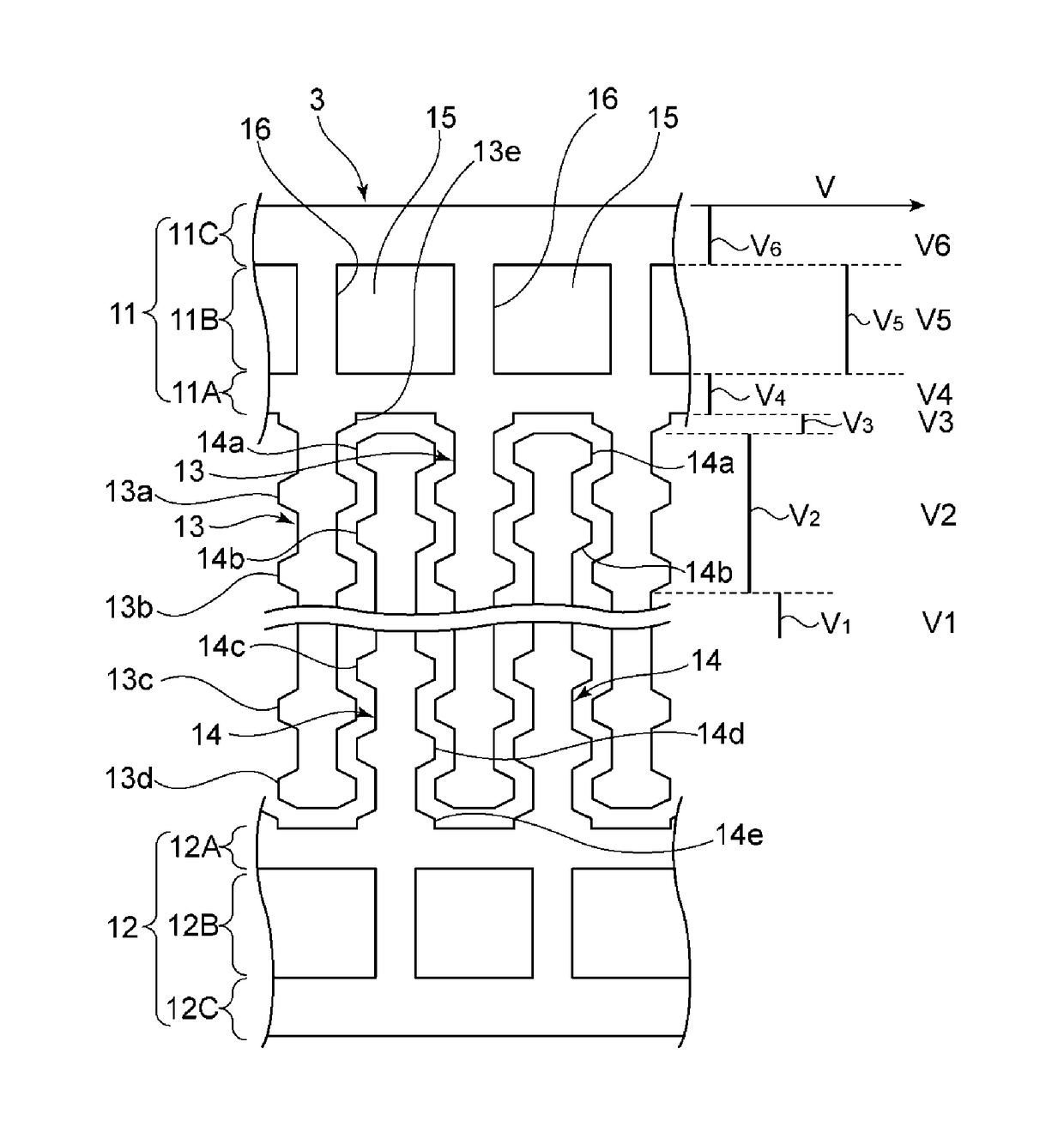
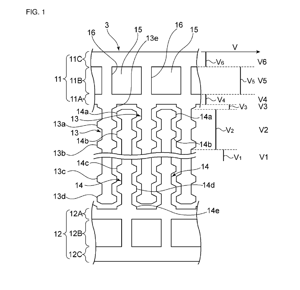
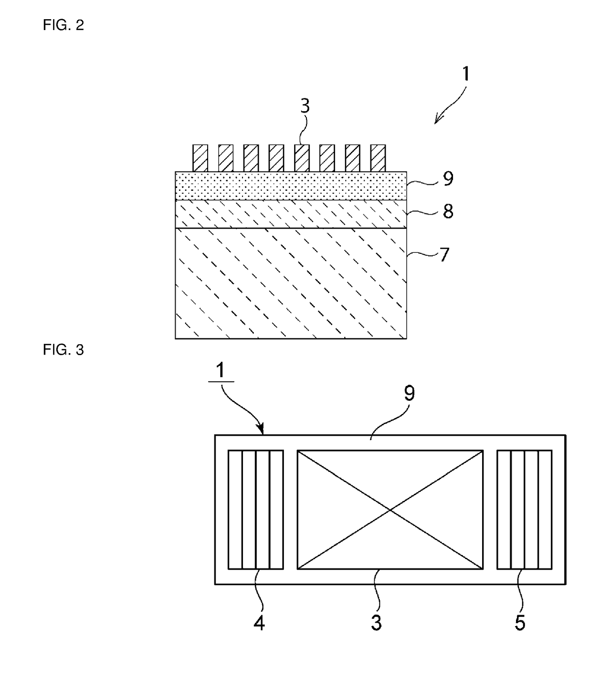
[0052]FIG. 1 is a partial cutaway plan view of a main portion of an elastic wave device according to a first preferred embodiment of the present invention. FIG. 2 is a schematic front sectional view thereof. FIG. 3 is a schematic plan view of the elastic wave device according to the first preferred embodiment.

[0053]As shown in FIG. 2, an elastic wave device 1 includes a high acoustic velocity supporting substrate 7 serving as a high acoustic velocity material. The high acoustic velocity supporting substrate 7 is made of Si. A low acoustic velocity film 8 in ...


PUM


Abstract

An elastic wave device includes a low acoustic velocity film, a piezoelectric film, and an IDT electrode, which are laminated on a high acoustic velocity material. In the IDT electrode, first electrode fingers, or second electrode fingers, or each of the first electrode fingers and the second electrode fingers, includes a wide width portion with a dimension in a width direction larger than a dimension at a center in a length direction and being provided closer to at least one of a side of a proximal end and a side of a distal end than a central region, at least one of a first busbar and a second busbar includes cavities arranged in a busbar length direction, and at least one of the first busbar and the second busbar includes an inner busbar portion which is positioned closer to a side of the first electrode fingers or a side of the second electrode fingers than the cavities are and which extends in the length direction of the first busbar and the second busbar, a central busbar portion that includes the cavities, and an outer busbar portion.

Description

CROSS REFERENCE TO RELATED APPLICATIONS[0001]This application claims the benefit of priority to Japanese Patent Application No. 2014-241810 filed on Nov. 28, 2014 and is a Continuation Application of PCT Application No. PCT / JP2015 / 079837 filed on Oct. 22, 2015. The entire contents of each application are hereby incorporated herein by reference.BACKGROUND OF THE INVENTION[0002]1. Field of the Invention[0003]The present invention relates to an elastic wave device preferably for use in, for example, a resonator or a bandpass filter.[0004]2. Description of the Related Art[0005]Hitherto, elastic wave devices have been widely used as resonators or bandpass filters. Japanese Unexamined Patent Application Publication No. 2011-101350 and WO2011 / 088904 below disclose a structure of a surface acoustic wave device that suppresses a spurious component in transverse modes by providing a piston mode. For example, in FIG. 9 in Japanese Unexamined Patent Application Publication No. 2011-101350 and i...

Claims


Application Information

Patent Timeline
IPC IPC(8): H03H9/02H03H9/54H03H9/145
CPCH03H9/02818H03H9/54H03H9/14541H03H9/02992H03H9/1457H03H9/02574H03H9/1092H03H9/125H03H9/145
Inventor IWAMOTO, HIDEKIOKADA, KEIJITAKAMINE, YUICHITAKAI, TSUTOMU
Owner MURATA MFG CO LTD
Learn More