Terminal apparatus, base station apparatus, and method
- Summary
- Abstract
- Description
- Claims
- Application Information
AI Technical Summary
Benefits of technology
Problems solved by technology
Method used
Image

Examples
first embodiment
[0029]A first embodiment of the present invention will be described below. A base station apparatus (a base station, a NodeB, or an eNodeB (eNB)) and a terminal apparatus (a terminal, a mobile station, a user apparatus, or a user equipment (UE)) are described referring to a communication system (a cellular system) that performs communication in a cell.
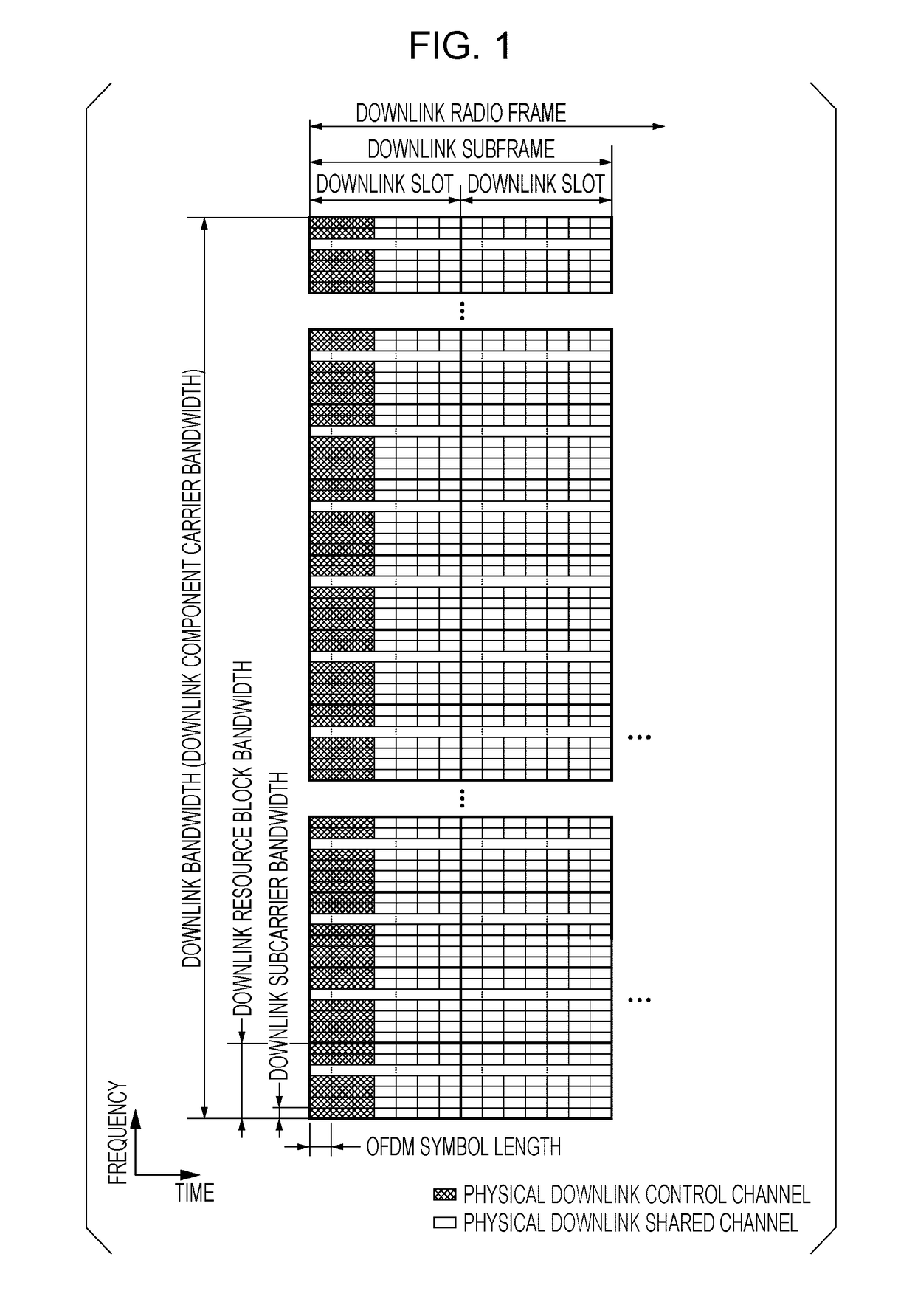
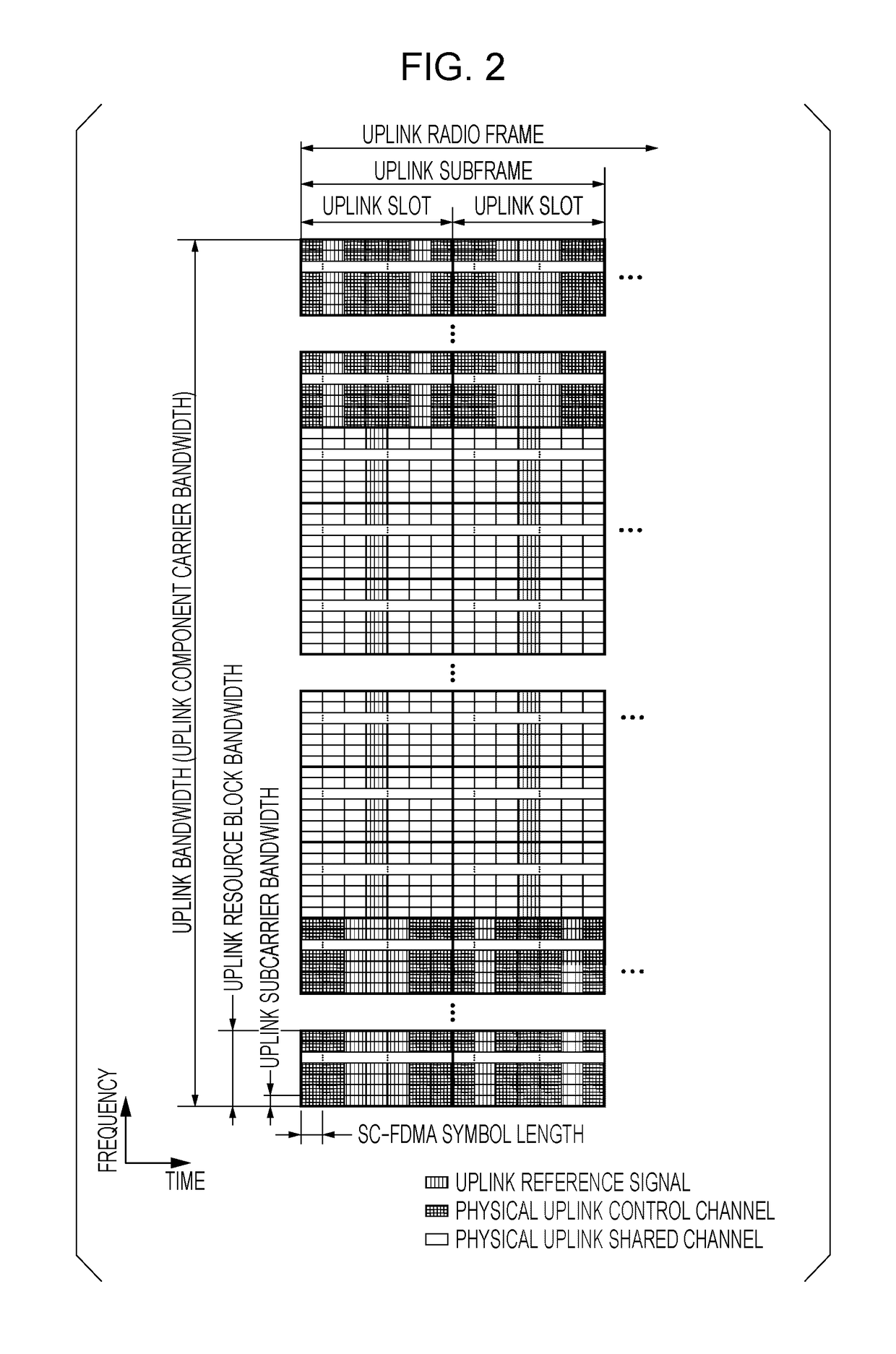
[0030]Main physical channels and physical signals that are used in EUTRA and Advanced EUTRA are described. A channel means a medium that is used for signal transmission, and a physical channel means a physical medium that is used for the signal transmission. According to the present invention, the physical channel and the signal can be used synonymously. There is a likelihood that in EUTRA and Advanced EUTRA, the physical channel will be added in future or an architecture or format type thereof will be changed or added, but this change or addition does not have any influence on a description of the present embodiment.
[0031]In EUTRA and...
second embodiment
[0292]Next, a second embodiment of the present invention will be described below.
[0293]According to the second embodiment, a transmission timing of the PRACH in a case where multiple CGs are configured, and the transmit power control by the terminal apparatus when the PRACH transmission and the PUSCH / PUCCH / PRACH transmission overlap among multiple CGs are described.
[0294]In a case where the PRACH transmission and the PUSCH / PUCCH transmission overlap among multiple CGs that are synchronous / asynchronous, the power is preferentially allocated to the transmission of the Physical Uplink Channel that is allocated in advance. For example, in a case where the PRACH transmission and the PUSCH transmission overlap, if the PUSCH transmission is assumed to be allocated in advance, regardless of priority levels of the Physical Uplink Channels, the power is preferentially allocated to the PUSCH transmission, and the remaining power is allocated to the PRACH transmission. If the remaining power is...
third embodiment
[0326]Next, a third embodiment is described. According to a third embodiment, in a case where the transmission of the PRACH (the preamble) is requested by the higher layer, if a request for the PRACH transmission is assumed to be triggered by the higher layer signal or the PDCCH order, the terminal apparatus for which multiple CGs are configured allocates the transmit power to the PRACH transmission in the subframe i in a certain serving cell (here, the first serving cell that belongs to the first CG) that belongs to a certain CG. At that time, if sufficient time (the sufficient number of subframes) is available between triggering and transmitting the request for the PRACH transmission, although the transmission of the uplink signal (for example, the PUSCH or the PUCCH) for a serving cell (here, the second serving cell that belongs to the second CG) that belongs to another CG occurs, the power is preferentially allocated to the PRACH. When the transmit power for the PRACH at that ti...
PUM
 Abstract
Description
Claims
Application Information
 - Generate Ideas
- Intellectual Property
- Life Sciences
- Materials
- Tech Scout
- Unparalleled Data Quality
- Higher Quality Content
- 60% Fewer Hallucinations
Browse by: Latest US Patents, China's latest patents, Technical Efficacy Thesaurus, Application Domain, Technology Topic, Popular Technical Reports.
© 2025 PatSnap. All rights reserved.Legal|Privacy policy|Modern Slavery Act Transparency Statement|Sitemap|About US| Contact US: help@patsnap.com