Observation device

a technology of observation device and capillary, which is applied in the field of observation device, can solve the problem of insufficient capillary resolution

Active Publication Date: 2017-08-17
OLYMPUS CORP
View PDF0 Cites 6 Cited by
  • Summary
  • Abstract
  • Description
  • Claims
  • Application Information

AI Technical Summary

Benefits of technology

[0007]One aspect of the present invention provides an observation device that includes a light source unit capable of adjusting a quantity of illuminating light in a B range that spans from a wavelength of 390 nm to 490 nm according to a first B range and a second B range having a longer wavelength than the first B range; and an imaging element that images reflected light from a subject irradiated with illuminating light emitted from the light source unit. The light source unit changes a ratio of a light quantity in the first B range to a light quantity in the second B range depending on whether white light imaging is conducted or narrow band imaging is conducted, and the imaging element includes RGB color filters arranged according to pixels and the R color filter transmits more light in an R range and the first B range than light in the second B range and has a spectral characteristic that satisfies conditional formulae (1) and (2):

Problems solved by technology

When such observation is performed by using color filters arranged in a primary color Bayer array in which B pixels account for only one quarter of all pixels, the resolution of capillaries is insufficient.

Method used


Image

  • Observation device
  • Observation device
  • Observation device

Examples


first embodiment

[0018]An observation device 1 according to the present invention will now be described with reference to the drawings.

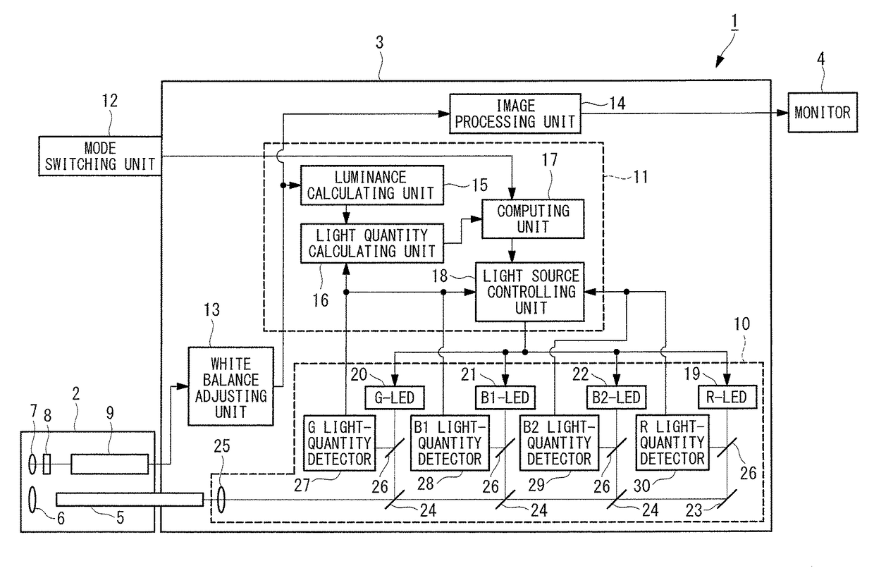
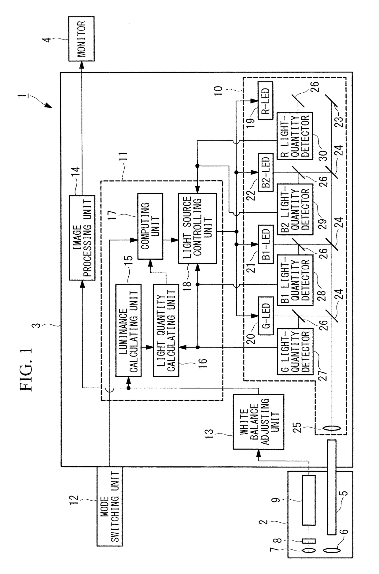
[0019]The observation device 1 according to this embodiment is, for example, an endoscopic device and, as illustrated in FIG. 1, includes a long, thin insertion portion 2 to be inserted into the body, a device main system 3 connected to a proximal end side of the insertion portion 2, and a monitor 4.

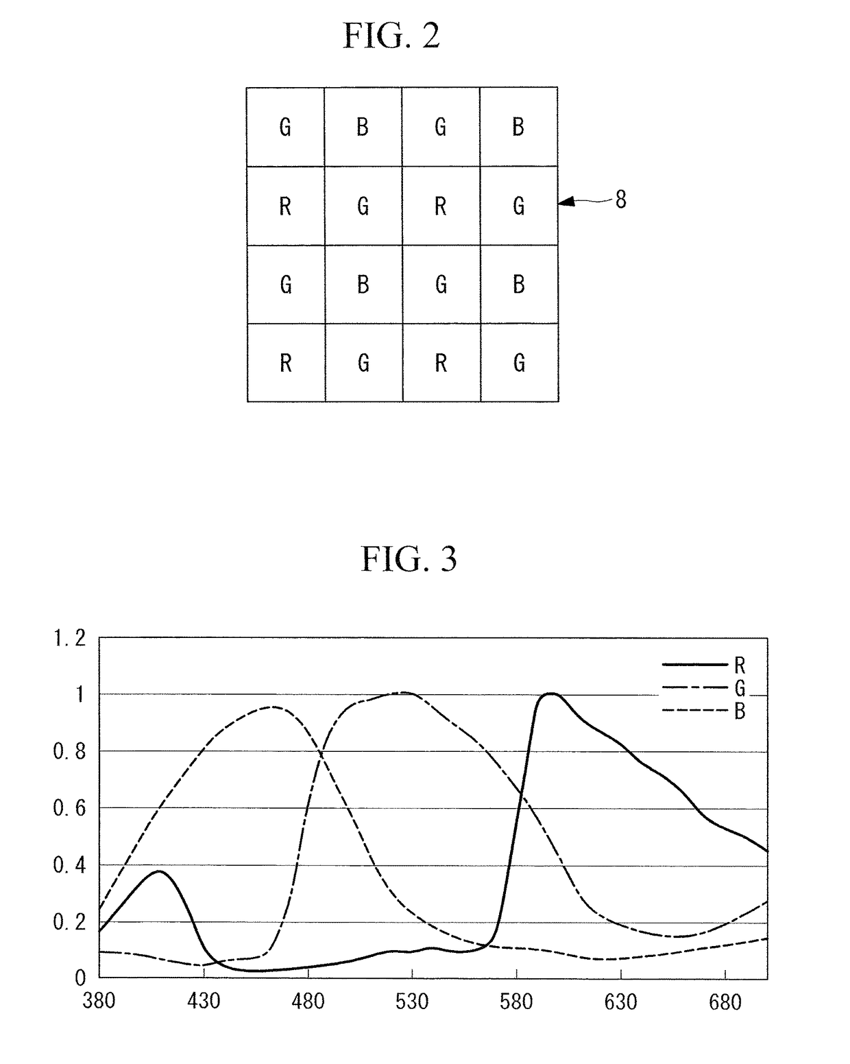
[0020]The insertion portion 2 includes an optical fiber 5 that extends through almost the entire length in the longitudinal direction to guide illuminating light, an illuminating lens 6 that emits, from a distal end of the insertion portion 2, the illuminating light that has been guided through the optical fiber 5, an objective lens 7 that collects reflected light from the imaging subject in the body irradiated with the illuminating light, and an imaging element 8 that images the light collected by the objective lens 7. The insertion portion 2 also includes an A / D convert...

second embodiment

[0047]Next, an observation device 31 according to the present invention is described with reference to the drawings.

[0048]In the description of this embodiment, parts that are common to the structure of the observation device 1 according to the first embodiment described above are denoted by the same reference numerals and descriptions therefor are omitted.

[0049]As illustrated in FIG. 8, the observation device 31 according to this embodiment differs from the observation device 1 according to the first embodiment in that a light source unit 32 includes a lamp 33 instead of the LEDs 19, 20, 21, and 22, a filter switching unit 34, and a light quantity adjusting unit 35.

[0050]The lamp 33 emits light having a broad wavelength band, as shown in FIG. 9, and is, for example, a xenon lamp. The filter switching unit 34 includes a filter for white light imaging and a filter for narrow band imaging, which are switchable. The filter for white light imaging has a wavelength characteristic that al...


PUM


Abstract

An observation device includes a light source unit capable of adjusting a quantity of 390-490 nm illuminating light according to a B1 range and a B2 range having a longer wavelength than the B1 range, and an imaging element that images reflected light from a subject irradiated with illuminating light. The light source unit changes the light quantity ratio of the B1 range to the B2 range depending on whether white light imaging is conducted or narrow band imaging is conducted. The imaging element includes RGB color filters arranged according to pixels and the R color filter transmits more light in an R range and the B1 range than light in the second B range and has a spectral characteristic that satisfies a predetermined conditional formulae.

Description

CROSS-REFERENCE TO RELATED APPLICATIONS[0001]This is a continuation of International Application PCT / JP2015 / 079432, with an international filing date of Oct. 19, 2015, which is hereby incorporated by reference herein in its entirety. This application claims the benefit of Japanese Patent Application No. 2014-235625, the content of which is incorporated herein by reference.TECHNICAL FIELD[0002]The present invention relates to an observation device.BACKGROUND ART[0003]A special optical observation technique, such as narrow band imaging (NBI) and blue laser imaging (BLI), that facilitates detection of lesions is known. Observation according to this technique involves irradiating a observation site with narrow band light and imaging the light reflected therefrom. In white light imaging, an endoscope that uses an image sensor equipped with color filters arranged in a primary color Bayer array is used to enable simultaneous observation while maintaining excellent color reproduction.[0004]...

Claims


Application Information

Patent Timeline
Patent Type & Authority Applications(United States)
IPC IPC(8): A61B5/00A61B1/07H05B33/08G02B5/20H05B37/02H04N5/225G02B23/24A61B1/05F21V8/00H05B44/00
CPCA61B5/0084A61B5/742A61B5/72A61B1/051A61B1/07H05B33/0815H04N2005/2255G02B6/0008H05B37/0227H04N5/2256G02B23/2469G02B5/201G02B23/2484H05B33/0842A61B1/00009A61B1/00186A61B1/0638A61B1/0646A61B1/0669A61B1/0684H05B47/00A61B1/0655H04N23/555H04N23/74H04N23/56
Inventor NAGAOKA, HIDEYUKI
Owner OLYMPUS CORP
Why Eureka
Try Eureka