
Use of no-bake mold process to manufacture side frame and bolster for a railway truck

a technology of side frame and bolster, which is applied in the field of railcar components, can solve the problems of reducing the draft angle of typical features of railroad components, and achieve the effect of increasing the fatigue li

Inactive Publication Date: 2017-08-17
NEVIS IND
View PDF4 Cites 9 Cited by
  • Summary
  • Abstract
  • Description
  • Claims
  • Application Information

AI Technical Summary

Benefits of technology

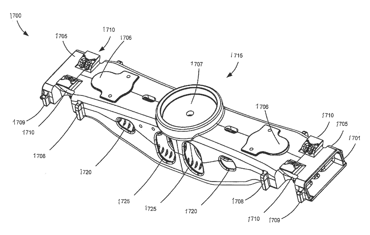
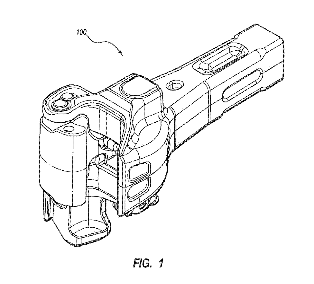
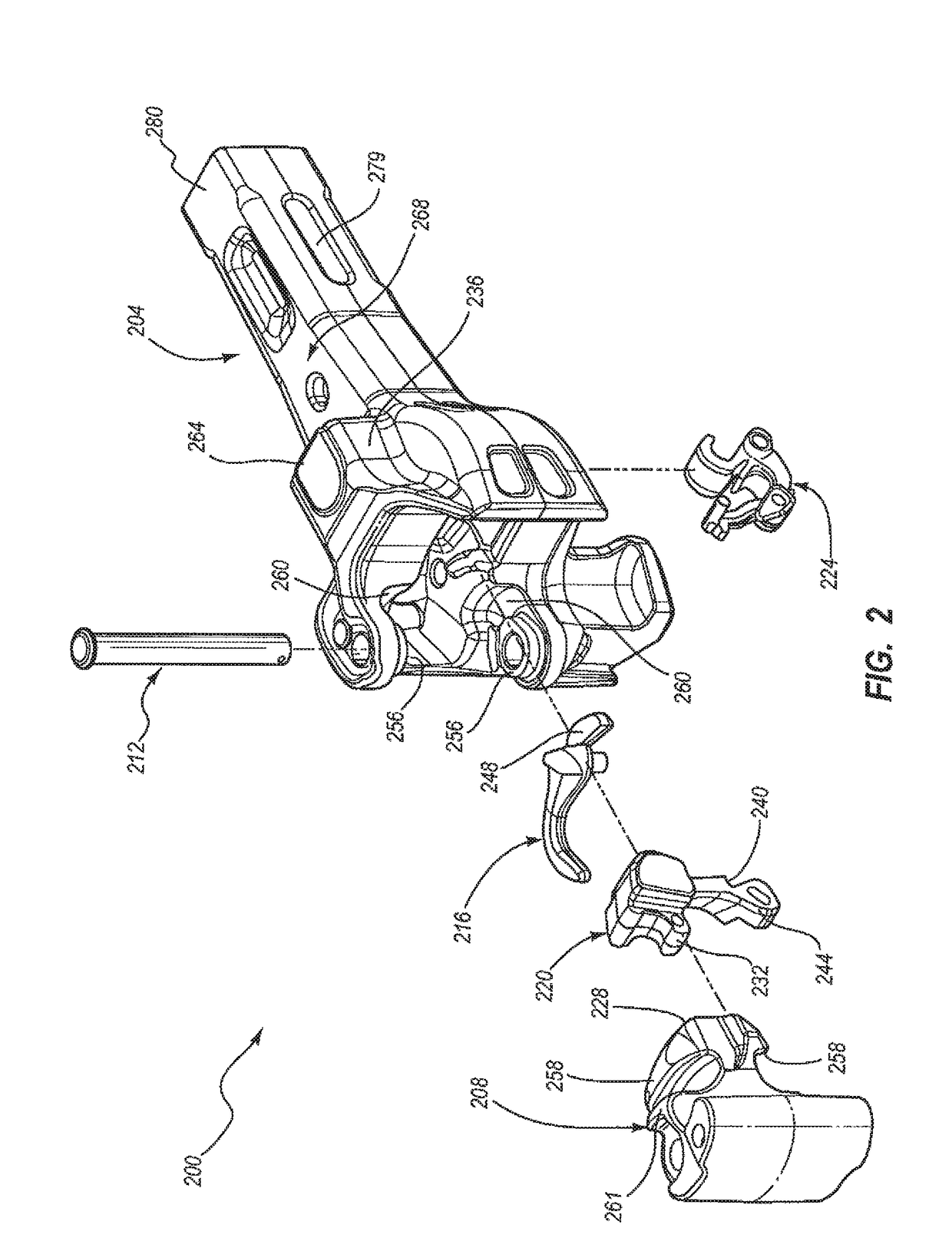
The invention is about a way to make railroad components like side frames or bolsters using a no-bake manufacturing process. This process uses a chemically-bonded sand system that creates a sand mold to cast the component. The result is a finished component that has a surface finish smoother than traditional methods. This leads to increased fatigue life compared to components made with green sand.

Problems solved by technology

According to some aspects, the method may result in reduced draft angles for typical features of the railroad component compared to a railroad component manufactured by a green sand process.

Method used


Image

  • Use of no-bake mold process to manufacture side frame and bolster for a railway truck
  • Use of no-bake mold process to manufacture side frame and bolster for a railway truck
  • Use of no-bake mold process to manufacture side frame and bolster for a railway truck

Examples


Embodiment Construction

[0056]In the following description of various example structures according to the invention, reference is made to the accompanying drawings, which form a part hereof, and in which are shown by way of illustration various example devices, systems, and environments in which aspects of the invention may be practiced. It is to be understood that other specific arrangements of parts, example devices, systems, and environments may be utilized and structural and functional modifications may be made without departing from the scope of the present invention. Also, while the terms “top,”“bottom,”“front,”“back,”“side,”“rear,” and the like may be used in this specification to describe various example features and elements of the invention, these terms are used herein as a matter of convenience, e.g., based on the example orientations shown in the figures or the orientation during typical use. Additionally, the term “plurality,” as used herein, indicates any number greater than one, either disju...


PUM

PropertyMeasurementUnit
shoe pocket anglesaaaaaaaaaa
depthsaaaaaaaaaa
depthsaaaaaaaaaa

Abstract

A method for casting a railroad component such as a component of a railway car truck. The component of the railway car truck may be, e.g., a side frame or a bolster of the railway car truck. The method includes manufacturing the railroad component made of steel in a no-bake manufacturing process including use of a chemically-bonded sand system that results in a sand mold from which the railroad component is cast. The railroad component resulting from the no-bake manufacturing process has a surface finish less than 750 micro-inches RMS, resulting in increased fatigue life compared to a railroad component manufactured by a green sand process.

Description

CROSS-REFERENCE TO RELATED APPLICATIONS[0001]This application is a continuation-in-part of U.S. patent application Ser. No. 14 / 739,857, filed Jun. 15, 2015, which is a continuation of U.S. patent application Ser. No. 14 / 337,722, filed Jul. 22, 2014, issued as U.S. Pat. No. 9,079,590; which is a continuation of U.S. patent application Ser. No. 13 / 916,114, filed Jun. 12, 2013, issued as U.S. Pat. No. 8,783,481; which is a continuation of U.S. patent application Ser. No. 12 / 685,346, filed Jan. 11, 2010, issued as U.S. Pat. No. 8,485,371. This application is also a continuation-in-part of U.S. patent application Ser. No. 14 / 943,269, which is a continuation of U.S. patent application Ser. No. 13 / 109,843, filed May 17, 2011, issued as U.S. Pat. No. 9,216,450. This application is also a continuation-in-part of U.S. patent application Ser. No. 15 / 152,860, filed May 12, 2016. The disclosures of the foregoing applications are herein incorporated by reference in their entirety.TECHNICAL FIELD[...

Claims


Application Information

Patent Timeline
Patent Type & Authority Applications(United States)
IPC IPC(8): B22C9/02B22D25/02B22C9/24B61F5/52B22C1/00
CPCB22C9/02B61F5/52B61G3/06B22C9/24B22D25/02B22C1/00B22C9/10B22C9/103B22C9/108
Inventor NIBOUAR, F. ANDREWSMERECKY, JERRY R.SELLBERG, RONALD P.GIBEAUT, ARTHUR A.GOTLUND, ERIK L.WERNER, MAUREENMAKARY, VAUGHNJEAMBEY, JON R.PIKE, JAMES A.BRYANT, JASON C.STULL, JONATHAN A.KURTZHALS, WILLIAM A.MANIBHARATHI, ROSHAN N.
Owner NEVIS IND
Learn More