Vehicle air intake apparatus, and methods of use and manufacture thereof

a technology of air intake apparatus and air intake chamber, which is applied in the direction of vehicle components, vehicle heating/cooling devices, transportation and packaging, etc., can solve the problems of insufficient water drainage from the air compartment, inability to adequately drain water, and inability to pass or supply overly humid air and/or water particles, etc., to facilitate the removal of an amount of water and enhance the effect of water removal

Active Publication Date: 2017-08-17
HONDA MOTOR CO LTD
View PDF4 Cites 6 Cited by
  • Summary
  • Abstract
  • Description
  • Claims
  • Application Information

AI Technical Summary

Benefits of technology

[0009]Some embodiments facilitate removal of an amount of water from the overly saturated air by providing a shield at a certain location within the air compartment. Some of these embodiments provide the shield within the air compartment generally between an entry opening of the drain and an intake from the air compartment into the HVAC system and / or passenger compartment. The shield disposed at this location can also be configured to intercept some or all of the air traveling from the drain toward the intake leading to the HVAC system and / or passenger compartment. This interception (e.g., contact between the overly saturated air and the shield) can result in removal of an amount of water from the overly saturated air, which may then be supplied to the HVAC system and / or passenger compartment.
[0010]Some of these embodiments can be configured to cause the overly saturated air to additionally be intercepted by another surface or surfaces, such as surface(s) that define the air compartment. In some embodiments, this other surface is constituted by a surface of a dashboard upper side member, which defines an end of the air compartment. This surface of the dashboard upper side member may generally oppose the shield, such that air traveling from and / or adjacent the drain is intercepted by both the surface of the dashboard upper side member and the shield so as to remove an amount of water from the overly saturated air.
[0011]Embodiments are intended to include or otherwise cover any and all methods and apparatus to direct air from areas at or adjacent the drain toward the surface of the dashboard upper side member. Some of these embodiments include a deflector disposed within the air compartment and over the drain. In some of these embodiments, the deflector is disposed to cover the upper opening of the drain, defines a concavity over the drain, and is configured to define an opening generally facing the surface of the dashboard upper side member. This opening can be configured to direct air traveling from the drain and through the concavity toward the surface of the dashboard upper side member. The air impacting the surface of the dashboard upper side member is thereby directed toward the shield to thereby also impact the shield. Impacting both the surface of the dashboard upper side member and the shield enhances removal of water from the overly saturated air traveling from areas at or around the drain.

Problems solved by technology

Under certain circumstances, the air supplied to the passenger compartment may entrain an undesirably high amount of water (hereinafter overly saturated air), resulting in the passage or supply of overly humid air and / or water particles, such as to the passenger compartment.
For example, drainage of the water from the air compartment may not be sufficiently effective to prevent the air in the air compartment from entraining too much water.
Wet surfaces within the compartment may also be responsible for this undesirably high water entrainment.

Method used


Image

  • Vehicle air intake apparatus, and methods of use and manufacture thereof
  • Vehicle air intake apparatus, and methods of use and manufacture thereof
  • Vehicle air intake apparatus, and methods of use and manufacture thereof

Examples


Embodiment Construction

[0034]A few inventive aspects of the disclosed embodiments are explained in detail below with reference to the various figures. Exemplary embodiments are described to illustrate the disclosed subject matter, not to limit its scope, which is defined by the claims. Those of ordinary skill in the art will recognize a number of equivalent variations of the various features provided in the description that follows. In the drawings, like reference numerals are used to identify like or identical components in the various views of the embodiments.

I. Vehicle Frame

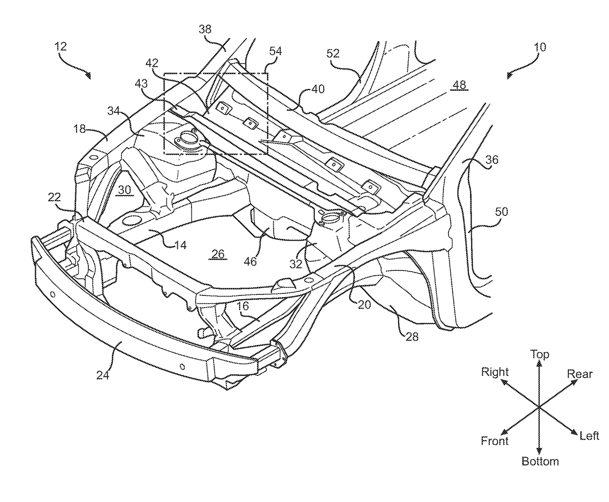
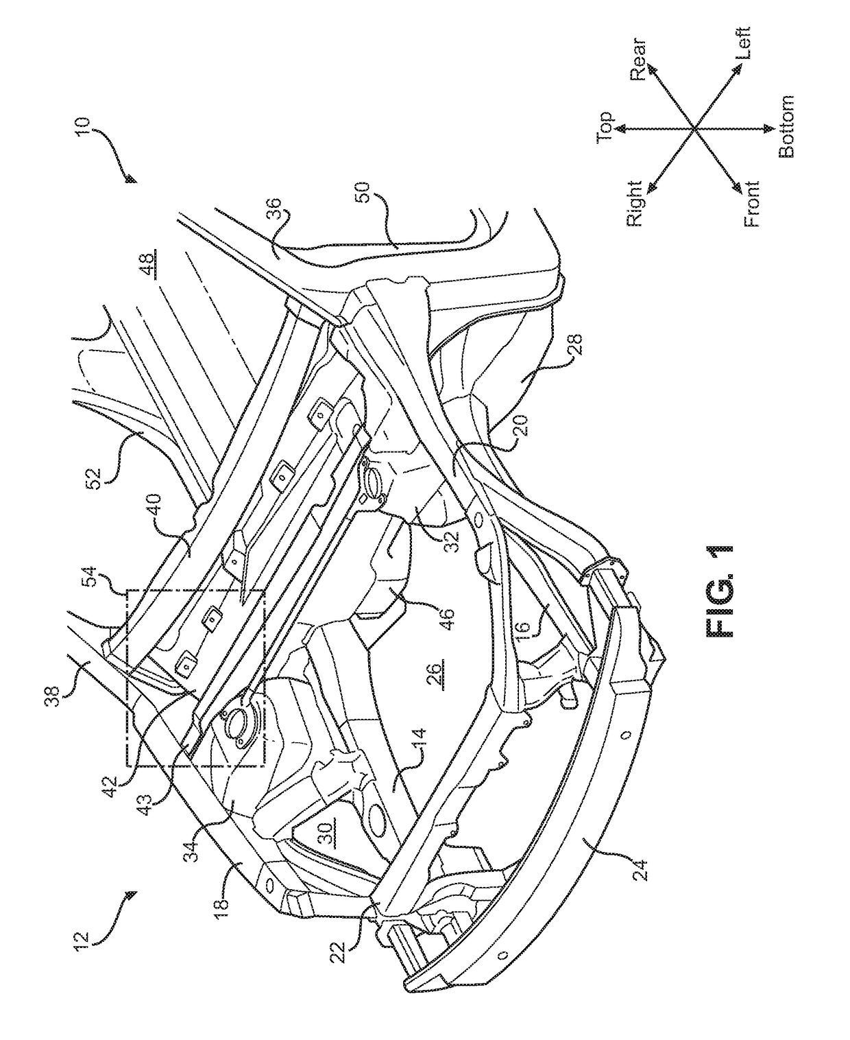
[0035]FIG. 1 is perspective view of a vehicle front end frame assembly 12. The front end frame assembly 12 of a vehicle 10 can include structural paths that are typically designed to support vehicle components as well as transfer energy from a site of a front impact in a controlled manner to the remaining frame and body of the vehicle 10. The front end frame assembly 12 can surround an engine compartment 26. For clarity of the discl...


PUM


Abstract

Some embodiments are directed to a deflector for use with a vehicle air intake system that directs air from a vehicle exterior to a vehicle interior. The deflector can include a base configured for attachment to a region of an interior wall of an air compartment adjacent a perimeter of a drain. The deflector can also include a barrier wall connected to the base and including an inner surface that is disposed over the drain when the base is attached to the interior wall of the air compartment. The barrier wall can be shaped to define a concavity between the drain and the inner surface. The barrier wall can define an air stream opening that is disposed to direct air traveling from the drain and through the concavity toward a section of the interior wall of the air compartment that opposes a shield.

Description

BACKGROUND[0001]The disclosed subject matter relates to vehicle air intake apparatus, and methods of use and manufacture thereof. In particular, the disclosed subject matter relates to methods and apparatus for directing air traveling toward an intake of a vehicle heating, ventilating, and / or air conditioning (HVAC) system for ultimate delivery to a vehicle passenger compartment.[0002]Many types of vehicles, including but not limited to vehicles that travel on land, include HVAC systems to provide air to a vehicle passenger compartment. This air can be provided directly to the passenger compartment, such as for ventilation, to enhance the supply of fresh air, and / or can be heated, cooled, etc., to achieve a desired climate within the passenger compartment. The impact of the supply and / or conditioning of the air can be especially pronounced or beneficial in the context of closed passenger compartments.SUMMARY[0003]The source of the air can be disposed at a variety of locations around...

Claims


Application Information

Patent Timeline
Patent Type & Authority Applications(United States)
IPC IPC(8): B60H1/28
CPCB60H1/28
Inventor MITCH, THOMASPOWERS, MARCMIHOK, KYLE
Owner HONDA MOTOR CO LTD
Why Eureka
Try Eureka