Vehicle control apparatus

Active Publication Date: 2017-08-17
TOYOTA JIDOSHA KK
View PDF1 Cites 33 Cited by
  • Summary
  • Abstract
  • Description
  • Claims
  • Application Information

AI Technical Summary

Benefits of technology

[0017]With this configuration, the warning is canceled in a case when the driver is determined not to be in the abnormal state by being determined that the aforementio

Problems solved by technology

Therefore, a problem arises that there is a possibility that it becomes impossible to cancel the driving support if t

Method used


Image

  • Vehicle control apparatus
  • Vehicle control apparatus
  • Vehicle control apparatus

Examples


first embodiment

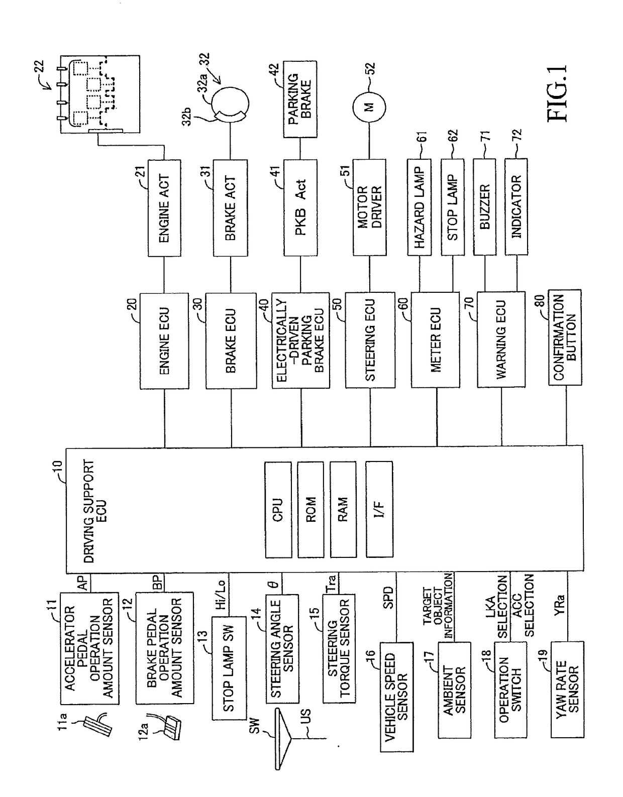
[0067]A vehicle control apparatus according to the first embodiment of the present invention (hereinafter, may be referred to as a “first apparatus”) is, as shown in FIG. 1, applied to a vehicle (hereinafter, may be referred to as an “own vehicle” in order to distinguish it from other vehicles), and comprises a driving support ECU 10, an engine ECU 20, a brake ECU 30, an electrically-driven parking brake ECU 40, a steering ECU 50, a meter ECU 60, and a warning ECU 70. Each of the ECUs is an electric control unit comprising a microcomputer as a main part. Those ECUs are connected via CAN (Controller Area Network) which is not illustrated so that the ECUs are capable of mutually transmitting and receiving information. In the present specification, the microcomputer includes CPU, ROM, RAM, a non-volatile memory, an interface I / F, or the like. The CPU is configured to realize / perform various functions by executing instructions (i.e., programs or routines) stored in the ROM.

[0068]The dri...

second embodiment

[0195]Next, a vehicle control apparatus (hereinafter, may be referred to as a “second apparatus”) according to the second embodiment of the present invention will be described. The second apparatus is different from the first apparatus mainly in that the second apparatus performs the abnormality determination of the driver using the confirmation button 80 regardless of whether or not the traffic lane keeping control and the trailing inter-vehicle distance control are being performed, and in that the second apparatus performs the prohibition of the acceleration override and the deceleration control when it is determined that the driver has become the abnormal state (when it is confirmed / finalized that the driver is determined to be in the abnormal state). Hereinafter, a description will be made, focusing on these differences.

[0196]CPU of ECU 45 in the second apparatus is configured to perform routines shown by flowcharts in FIG. 14 to FIG. 16 every time a predetermined period of time...

third embodiment

[0219]Next, a vehicle control apparatus (hereinafter, may be referred to as a “third apparatus”) according to the third embodiment of the present invention will be described. The third apparatus is different from the first apparatus in that the third apparatus adopts so-called a “steer-by-wire system”, it invalidates the operation of the steering wheel as well as the operation of the accelerator pedal when the determination that the driver is in the abnormal state has been confirmed / finalized, and it determines whether or not the specific driving operation has occurred based on the operation of the steering wheel after the point in time (the abnormality determination point in time, the abnormality determination confirmation / finalized time) at which the determination that the driver abnormality occurred has been confirmed / finalized. Hereinafter, a description will be made, focusing on these differences.

[0220]The steer-by-wire system which the third apparatus adopts is a steering whee...


PUM


Abstract

Driving support ECU determines that a driver is in an abnormal state when a state where a steering amount correlation value which changes when a steering wheel SW of a vehicle is operated does not change continues over more than or equal to an abnormality determination threshold time. When the driver is determined to be in the abnormal state, the ECU decelerates the vehicle, makes a hazard lamp blink and invalidates an acceleration request based on a change in an operation amount of an accelerator pedal. The ECU terminates decelerating of the vehicle and permits the acceleration override when a specific driving operation (an operation that the accelerator pedal changes from an operating state to a non-operating state and then again changes to the operating state within a predetermined threshold time) is determined to have occurred after the driver has been determined to be in the abnormal state.

Description

TECHNICAL FIELD[0001]The present invention relates to a vehicle control apparatus coping with a case where a driver has fallen into an abnormal state in which the driver loses an ability to drive a vehicle.BACKGROUND ART[0002]An apparatus has conventionally been proposed which determines whether or not a driver has fallen into an abnormal state where the driver loses an ability to drive a vehicle (for example, a drowsy driving state, a mental and physical failure state, or the like), and performs driving support when the driver is determined to be in such an abnormal state.[0003]For example, one of conventional apparatuses is configured to calculate a deviation ε of a future position from a target course position of a vehicle based on a shape of a traveling road and a position of the vehicle in a traveling lane, to detect a steering angle σ corresponding to a steering operation of the driver, to determine that the driver is in the abnormal state when a region represented by a combin...

Claims


Application Information

Patent Timeline
IPC IPC(8): B60W50/08B60W50/14B60W40/08B60W30/12
CPCB60W50/082B60W30/12B60W50/14B60W40/08B60W2540/12B60W2540/26B60W2710/20B60W2420/42B60W2420/52B60W2040/0818B60W2540/10G05D1/0214G05D1/0251G05D1/0257G05D1/0276G05D2201/0213B60W50/10B60W30/16B60W2540/103B60W2540/106B60W2540/18B60W10/20B60W2050/143B60K28/06
Inventor OTAKE, HIROTADA
Owner TOYOTA JIDOSHA KK
Why Eureka
Try Eureka