Automatic intelligent parking spot lock

An automatic parking lock technology, which is applied to buildings where cars are parked, comprehensive factory control, electrical program control, etc., can solve problems such as insufficient waiting time, and achieve the effects of reduced transmission torque, reduced cost, and reduced power consumption

Active Publication Date: 2014-09-10
YUYAO JINGCHENG HIGH & NEW TECH
View PDF6 Cites 9 Cited by
  • Summary
  • Abstract
  • Description
  • Claims
  • Application Information

AI Technical Summary

Problems solved by technology

[0005] In order to overcome the shortcoming that the existing intelligent parking lock switch needs to wai...

Method used


Image

  • Automatic intelligent parking spot lock
  • Automatic intelligent parking spot lock
  • Automatic intelligent parking spot lock

Examples


Embodiment 1

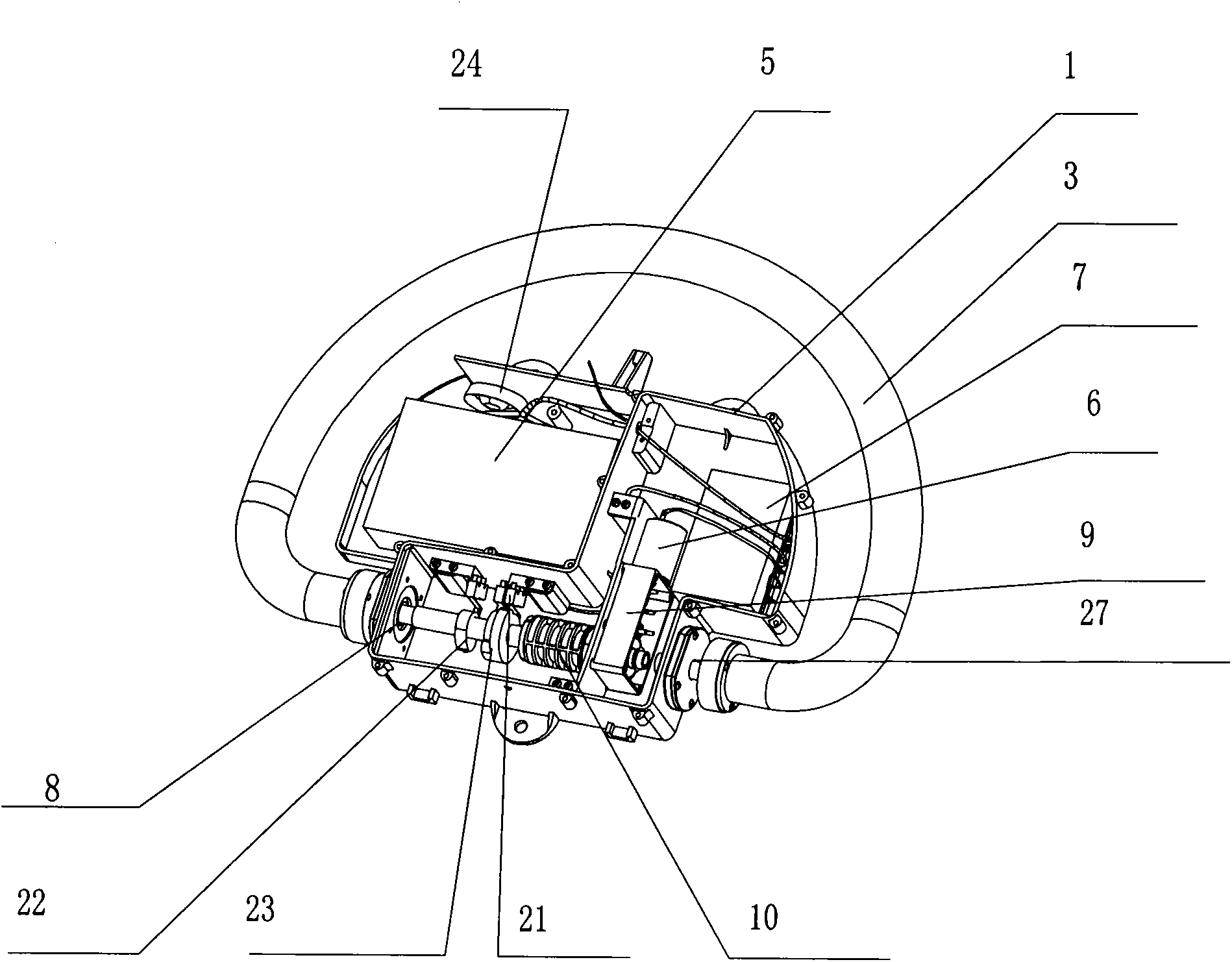
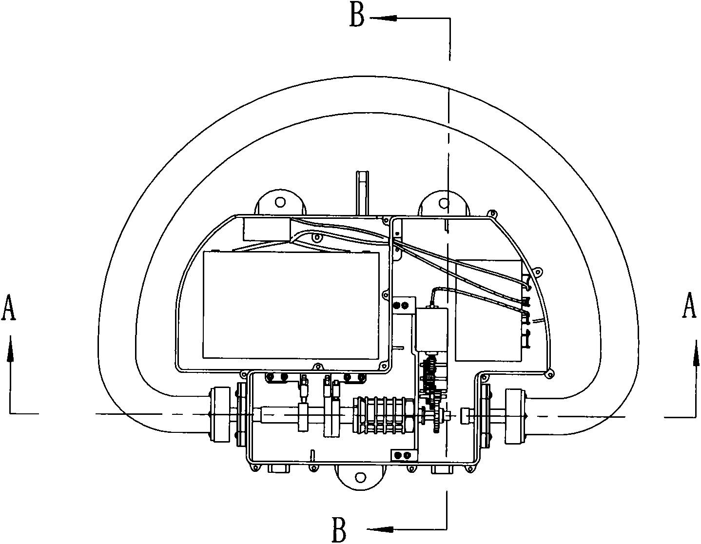
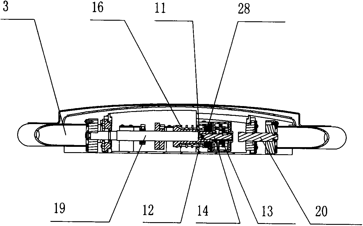
[0037] An automatic intelligent parking lock, which includes a box body 1, a box body upper cover 2, a blocking rocker arm 3, a transmission shaft 4, a power supply 5, a motor 6, and a control system 7; There is a shaft hole 8, the transmission shaft 4 passes through the shaft hole 8 and is connected to the blocking rocker arm 3, and the control system 7 is respectively connected to the power supply 5 and the motor 6 through electric wires; it also includes a deceleration assembly 9 and a clutch assembly 10, and the clutch assembly 10 includes Friction sleeve 11, connecting pin 12; friction sleeve 11 is nested on the transmission shaft 4, reduction assembly 9 includes an output wheel 13, an output shaft 14, a worm wheel 17, and a worm 15, and the worm wheel 17 is engaged with the worm 15, and the worm 15 is connected with the motor 6, and the output wheel 13 is nested on the output shaft 14 and connected with the worm wheel 17; the output shaft 14 is connected with the friction...

Embodiment 2

[0049] The control system includes an initial setting module 29, a signal receiving module 30, a data processing module 31, a lock release processing module 32, an uplock processing module 33, and a dormancy module 34; the data processing module 31 and the initial setting module 29, Signal receiving module 30, put lock processing module 32, erect lock processing module 33, dormancy module are connected; Data processing module 31 takes in operating parameters, initial setting module 29 reads operating parameters, initializes environment variable; Said signal receiving module 30 Connect with the signal receiver 30 through the data signal, and transmit the signal to the data processing module 31. When the correct card number is received, the data processing module 31 performs logic processing on receiving the card, and issues instructions to the lock release processing module 32 through the received signal. , carry out lock release logic processing, release lock processing module ...


PUM


Abstract

The invention provides an automatic intelligent parking spot lock, which overcomes the defect that the waiting is needed during the unlocking and the locking of the existing parking spot lock, so the speed is not high enough. The fast and automatic intelligent parking spot lock is provided and comprises a box body, a box body upper cover, a blocking rocker arm, a transmission shaft, a power supply, a motor and a control system, wherein shaft holes are respectively formed in the two opposite side surfaces of the box body; the transmission shaft passes through the shaft holes to be connected with the blocking rocker arm; the control system is respectively connected with the power supply and the motor through electric wires; the automatic intelligent parking spot lock also comprises a decelerating assembly and a clutch assembly; the clutch assembly comprises a friction sleeve and a connecting pin; the friction sleeve is nested on the transmission shaft; and the decelerating assembly comprises an output wheel, an output shaft and the like. The automatic intelligent parking spot lock has the advantages that the structural design is scientific and reasonable; the unlocking and the locking are convenient and fast; in addition, the automatic intelligent parking spot lock cannot be easily damaged; the service life is long; and the automatic intelligent parking spot lock is suitable to be popularized and applied.

Description

technical field [0001] The invention belongs to a space limiting device for parking, and in particular relates to an automatic intelligent parking space lock. Background technique [0002] A parking lock is a device for managing parking spaces. With the improvement of people's living standards, more and more people have private cars, and the problem of parking difficulties has become increasingly prominent. No matter in the parking lot or in the residential area, there is a problem of random parking of cars. In order to facilitate management and facilitate users to park nearby, rational use of parking spaces in the parking lot, using parking locks to limit is an effective and convenient way. [0003] Parking locks in the prior art are generally manual or semi-automatic devices. Manual parking locks are simple in structure and cheap in cost, but require users to manually unlock and lock them, which is inconvenient to use and takes a long time to park; Controlled by the remo...

Claims


Application Information

Patent Timeline
IPC IPC(8): E04H6/42G05B19/16
CPCY02P90/02
Inventor 陈国章
Owner YUYAO JINGCHENG HIGH & NEW TECH
Why Eureka
Try Eureka