Airflow sensor for a heat sink

a technology of airflow sensor and heat sink, which is applied in the direction of instruments, lighting and heating apparatus, measurement devices, etc., can solve the problems of difficult prediction and modeling of the internal environmen

Active Publication Date: 2017-08-17
IBM CORP
View PDF5 Cites 11 Cited by
  • Summary
  • Abstract
  • Description
  • Claims
  • Application Information

AI Technical Summary

Problems solved by technology

Oftentimes the internal environment is difficult to predict and model.

Method used


Image

  • Airflow sensor for a heat sink
  • Airflow sensor for a heat sink
  • Airflow sensor for a heat sink

Examples


Embodiment Construction

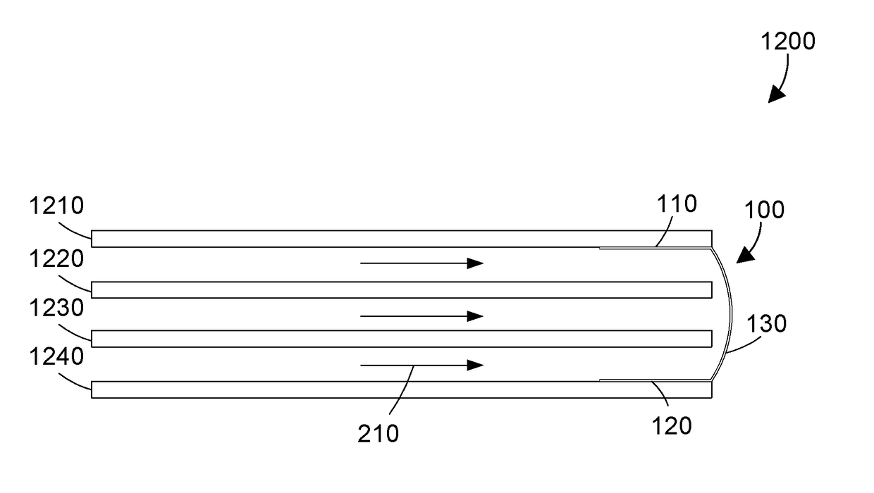
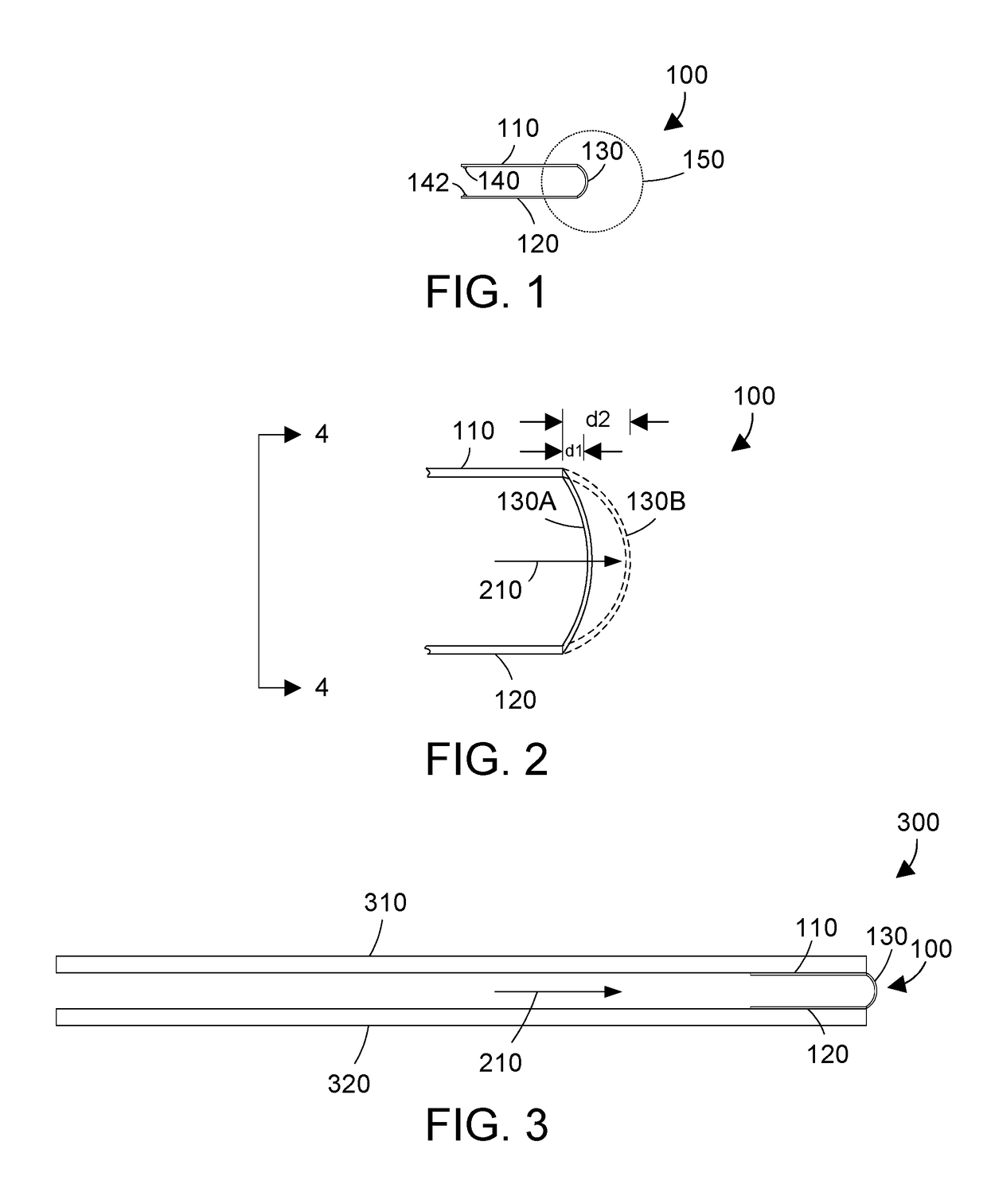
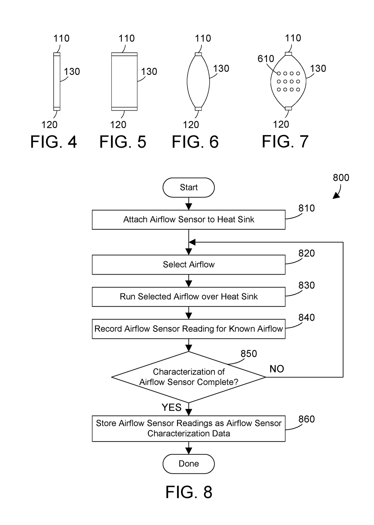
[0018]The disclosure and claims herein relate to an airflow sensor for a heat sink that has a first portion having a first electrical point of contact, a second portion have a second electrical point of contact, and a deformable portion made of an electroactive material electrically coupled to the first and second portions. The deformable portion has first electrical properties measured between the first and second electrical points of contact when there is no airflow and the deformable portion is in a first position, and has second electrical properties different than the first electrical properties when a source of airflow blows air against the deformable portion, thereby causing the deformable portion to extend to a second position farther away from the source of airflow than the first position. The airflow sensor can be incorporated into a heat sink for an electronic component.

[0019]Referring to FIG. 1, an airflow sensor 100 comprises a first portion 110, a second portion 120, a...


PUM


Abstract

An airflow sensor for a heat sink has a first portion having a first electrical point of contact, a second portion have a second electrical point of contact, and a deformable portion made of an electroactive material electrically coupled to the first and second portions. The deformable portion has first electrical properties measured between the first and second electrical points of contact when there is no airflow and the deformable portion is in a first position, and has second electrical properties different than the first electrical properties when a source of airflow blows air against the deformable portion, thereby causing the deformable portion to extend to a second position farther away from the source of airflow than the first position. The airflow sensor can be incorporated into a heat sink for an electronic component.

Description

BACKGROUND[0001]1. Technical Field[0002]This disclosure generally relates to airflow sensors, and more specifically relates to an airflow sensor for a heat sink.[0003]2. Background Art[0004]Heat sinks are commonly used in modern electronic systems to dissipate heat generated by electronic components, such as processors. A source of air such as a fan is typically placed in proximity to a heat sink to produce airflow over the heat sink, which enhances the ability of the heat sink to dissipate heat.[0005]Modern heat sinks are typically modeled using thermal simulation. Prototypes are then built, which are qualified with thermal test vehicles and flow benches. However, even with thermal simulation and flow bench qualification, a heat sink may behave differently in a system than modeled. Oftentimes the internal environment is difficult to predict and model.SUMMARY[0006]An airflow sensor for a heat sink has a first portion having a first electrical point of contact, a second portion have ...

Claims


Application Information

Patent Timeline
Patent Type & Authority Applications(United States)
IPC IPC(8): F28F27/00F28F3/02G01F1/69
CPCF28F27/00G01F1/69F28F2200/00F28D2021/0029F28F3/02G01F1/383G01F1/56
Inventor ANDERL, WILLIAM J.ELISON, BRET P.MANN, PHILLIP V.PETERSON, CHELSIE M.
Owner IBM CORP
Why Eureka
Try Eureka