
Signal decomposition, tracking, analysis, and reconstruction

a technology of signal decomposition and analysis, applied in the field of computer-implemented systems and methods, can solve the problems of large amounts of digital data that have little or no import, large amounts of digital data that requires relatively large amounts of space to store digitized data, and difficult to achieve high-fidelity digital representations

Active Publication Date: 2017-08-24
INT TECH CENT FZC
View PDF1 Cites 3 Cited by
  • Summary
  • Abstract
  • Description
  • Claims
  • Application Information

AI Technical Summary

Benefits of technology

The present invention is described in detail through a detailed description and accompanying drawing. This information will be useful for understanding the technical effects of the invention. The technical effects of the invention will be explained from the drawings and description.

Problems solved by technology

High-fidelity digital representations are problematic for a number of reasons.
First, they require relatively large amounts of space within which to store the digitized data.
Another problem with high-fidelity digital representations is that they can result in large amounts of digital data that has little or no import in terms of conveying meaning.
For example, a periodic wave signal that merely repeats the same waveform does not convey much meaning to the person analyzing the waveform, and may in fact just take up storage space with unremarkable data.
An additional problem is the repeated sampling, over sampling of such high-fidelity data even though it is otherwise unremarkable.
Such over sampling results in wasted processing bandwidth (i.e., processor cycles, and / or power) as well as data bandwidth (data storage space and / or transmission bandwidth).

Method used

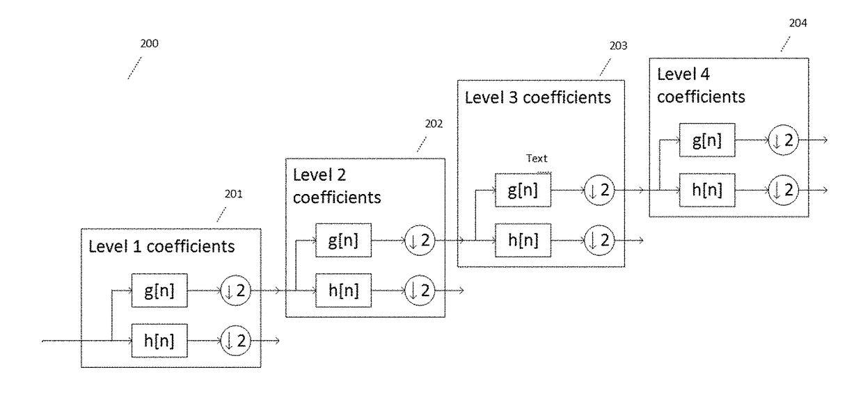
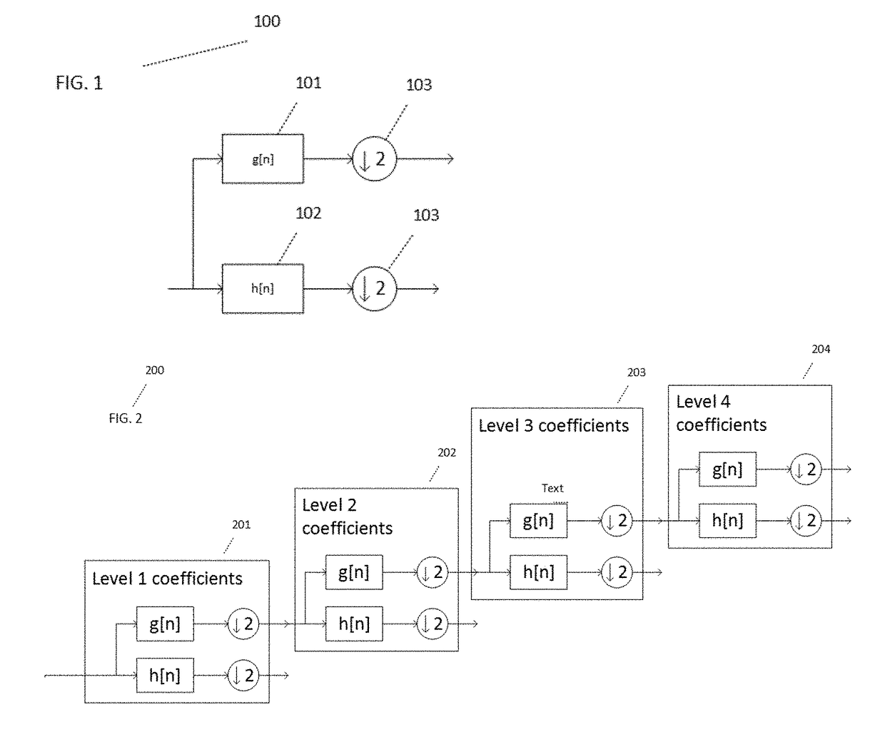
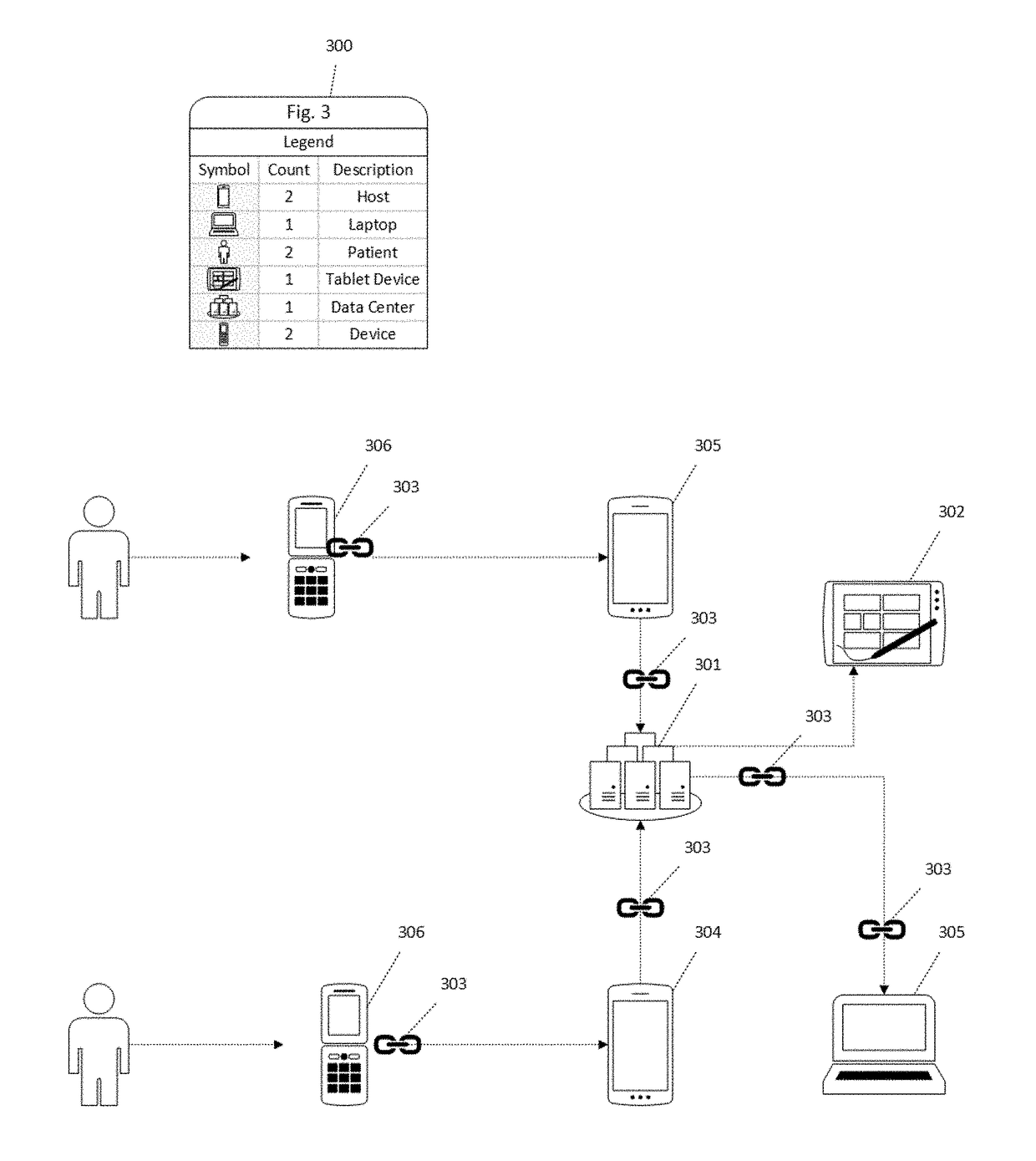

Image

  • Signal decomposition, tracking, analysis, and reconstruction
  • Signal decomposition, tracking, analysis, and reconstruction
  • Signal decomposition, tracking, analysis, and reconstruction

Examples


example

[0065]In some embodiments, the 50 / 60 Hz component (power net frequency) was removed from the electrocardiogram before its processing; moreover, the band pass filter of 0.5 . . . 40 Hz was used for the removal of trend and muscle tremor. ECG recording time was 2.5 hours, and the entire signal was divided into 5-minute segments. A sixteenth order linear prediction filter was used as a main signal processing procedure. Thus, a vector of 16 parameters was formed for each ECG.

[0066]The research was conducted on male volunteers suffering from type 2 diabetes. Number of volunteers: 75. Patients suffering serious heart muscle disorders were not involved. The standard oral glucose tolerance test was used as a basis. Research duration was 2.5 hours and included several stages. The research was conducted in the morning on an empty stomach. For this purpose, an examined volunteer was motionless and laid on his / her back during this research period. No manipulations were conducted with the patien...


PUM


Abstract

A system and method for representing quasi-periodic electrocardiography waveforms, wherein system employs a hybrid-coding scheme combining linear predictive coding techniques based upon Algebraic Code Excited Linear Prediction with a discrete wavelet transforms.

Description

FIELD OF THE INVENTION[0001]This invention relates to the field of computer-implemented systems and methods, and more specifically a software, embedded-circuits or firmware implemented system and method to decompose signals in a data structures to store such signals having quasi-periodic wave properties.BACKGROUND OF THE INVENTION[0002]The digital representation of waveforms is a technology that is central to various sectors of industry where the detection of periodic and non-periodic waveforms can be critical to determining whether an erratic heartbeat, electrical short circuit, or some other problem exists. A digital representation must clearly and accurately represent the analog source of a waveform, but at the same time be able to accomplish such things as, compressing the incoming data into some manageable size, and maintain the integrity of the incoming data (i.e., making sure that the digital representation has enough fidelity to the original signal to be useful). Of addition...

Claims


Application Information

Patent Timeline
IPC IPC(8): A61B5/00H04L29/08A61B5/1477A61B5/044A61B5/145G06F17/16A61B5/0245
CPCA61B5/7275G06F17/16H04L67/1097A61B5/0006A61B5/0245A61B5/7282A61B5/14532A61B5/1477A61B5/7278A61B5/7246A61B5/726A61B5/044A61B5/6846A61B5/6898G06F17/148G16H40/63G16H50/30G16H50/70
Inventor PULAVSKYI, ANATOLII
Owner INT TECH CENT FZC
Learn More