Spectrum-generation system based on multiple-diffraction optical phasometry

a technology of optical phasometry and spectral generation, applied in the field of optical guides, can solve problems such as not always feasibl

Inactive Publication Date: 2017-08-24
ZHEJIANG UNIV
View PDF28 Cites 3 Cited by
  • Summary
  • Abstract
  • Description
  • Claims
  • Application Information

AI Technical Summary

Problems solved by technology

While Campagna's system is relatively scalable, Campagna's system requires a user to place the ruler directly on top of the device requiring the guideline, which may not always be feasible.
Boyle's grid, however, needs to be projected using a beam that is cut into a strict 90 degree grid pattern and isn't able to project other types of patterns.

Method used


Image

  • Spectrum-generation system based on multiple-diffraction optical phasometry
  • Spectrum-generation system based on multiple-diffraction optical phasometry
  • Spectrum-generation system based on multiple-diffraction optical phasometry

Examples


embodiment 400

[0065]FIGS. 4 and 4B depict an alternative embodiment with filament grating system 400 having a light source 410, a filament 420, a filter 430, a grating 440, and a line scan camera 450. The filament is configured to exhibit diffraction phenomena based upon its material properties and dimensions. Embodiment 400 uses filament 420 as its first grating, filter 430 as its second grating, and grating 440 as its third grating. In system 400, parallel monochromatic light is diffracted first by filament 420. Filament 420 exhibits a diffraction phenomenon when light is incident on the filament which acts as a spatial light modulator. Filter 430 only allows bright stripes of ±m orders to pass through. The through-passed bright stripes are then diffracted by grating 440 into a plurality of dots onto line scan camera 450, which replaces surface 140. Line scan camera 450 detects each dot that is splayed on the surface.

(II.a) Contemplated Methods and Theoretic Formulas are Described Below.

[0066]T...

embodiment 500

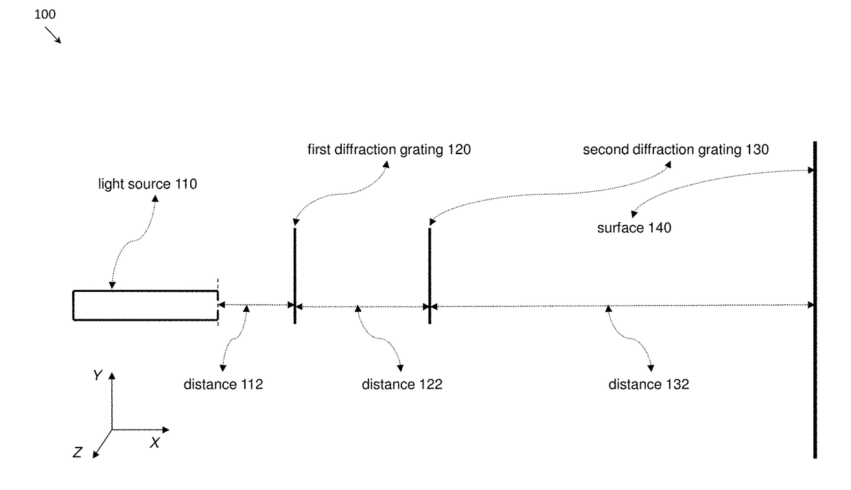
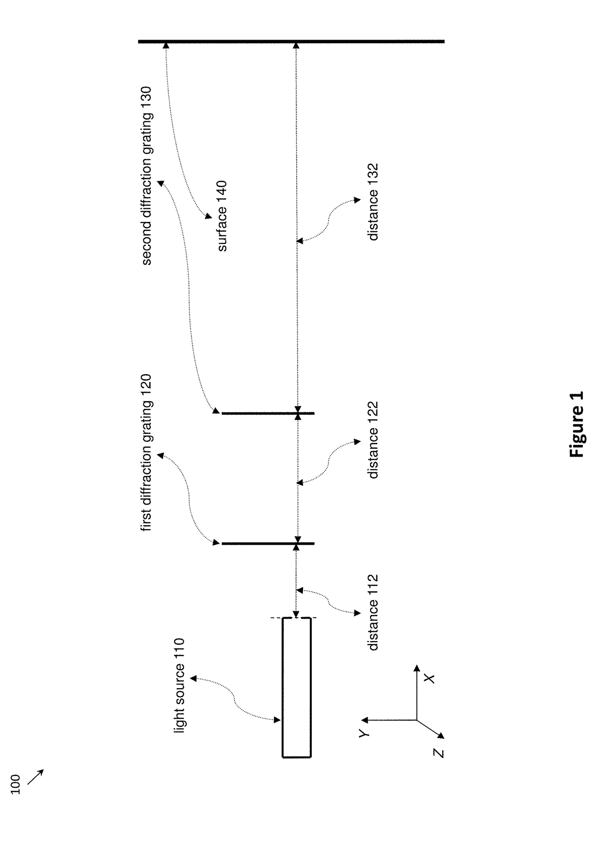
[0084]FIGS. 5A-5C show an embodiment 500 having a light source (not shown), a first grating 520, a second grating 530 and a surface 540, where the position of second grating 530 changes with respect to first grating 520 and surface 540, altering the characteristics of the optical pattern that is shown on surface 540. Each of the optical patterns have a “continuity” characteristic between the different surfaces when the distance between first grating 520 and second grating 530 changes. The setups in FIGS. 5A, 5B, and 5C, are each similar to the setup in FIG. 1. The salient differentiation among the three setups in FIGS. 5A, 5B, and 5C is the distance between the two gratings. The three setups show that when this distance changes, the optical patterns change to reflect the new position.

(III.b) the “Relatedness” Characteristic of the Multiple Components in an Optical Pattern.

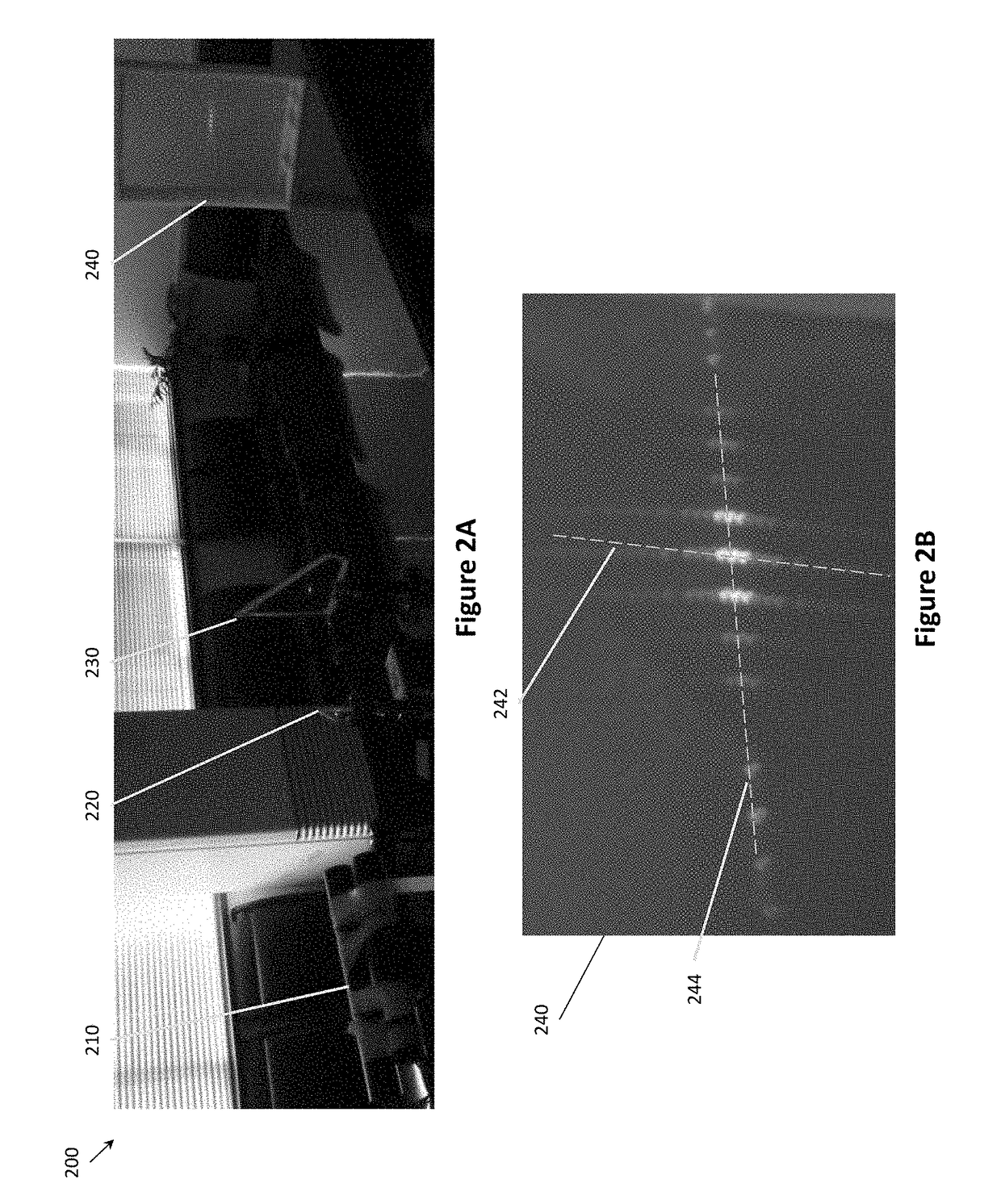
[0085]With the method in this inventive subject matter, an optical pattern typically has several visible compone...

second embodiment

[0089]A change in the orientation of one grating relative to the other grating can create an angled incidence, allowing a user to (a) measure the angle of an object being measured by the device and / or (b) ensure that an object is angled appropriately with respect to another object. For example, a user could shine a DDOP device on an object having an angle between two components, aligning one row of dots along one component and another row of dots along the second component. Then the user could analyze a computer system that tracks the orientation of one grating relative to the other grating in order to determine the angle between the two components being measured. In the second embodiment, the user could first set the orientation of one grating relative to the other grating (e.g. a 90 degree angle or a 45 degree angle) and then aim the DDOP device at two components that need to be oriented to that angle relative to one another. The user could then align the first component along the...


PUM


Abstract

An optical guide has at least two diffraction gratings in serial in front of a light source in order to diffract a light beam from the light source twice. The first diffraction grating could split the light beam into several parallel light beams along a first axis, and the second diffraction grating could split the light beams into several points of light along a second axis, and so on and so forth. By rotating the diffraction gratings relative to one another and by adjusting the distance between the diffraction gratings, a user of the optical guide could adjust the angle of the axis points and adjust a relative distance of the points of light relative to one another. These light beams could provide convenient guides for users in a variety of applications.

Description

FIELD OF THE INVENTION[0001]The field of the invention is optical guides.BACKGROUND[0002]The background description includes information that may be useful in understanding the present invention. It is not an admission that any of the information provided herein is prior art or relevant to the presently claimed invention, or that any publication specifically or implicitly referenced is prior art.[0003]All publications herein are incorporated by reference to the same extent as if each individual publication or patent application were specifically and individually indicated to be incorporated by reference. Where a definition or use of a term in an incorporated reference is inconsistent or contrary to the definition of that term provided herein, the definition of that term provided herein applies and the definition of that term in the reference does not apply.[0004]It is important to use accurate measurement instruments when affixing or constructing permanent or semi-permanent structur...

Claims


Application Information

Patent Timeline
Patent Type & Authority Applications(United States)
IPC IPC(8): G02B27/10G01C15/00
CPCG01C15/002G02B27/1093G01B9/00G01B11/00G01D5/347G02B27/20G02B27/4233G02B27/4277
Inventor CAO, XIANGQUNLIN, BINBAI, JIANCAO, YU
Owner ZHEJIANG UNIV
Why Eureka
Try Eureka