Switching regulator

a technology of switching regulator and output terminal, which is applied in the direction of electric variable regulation, process and machine control, instruments, etc., can solve the problems of failure of load connected to the output terminal b>6/b>, failure of feedback function, etc., and achieve the effect of preventing an output voltage from exceeding

Active Publication Date: 2017-08-24
ABLIC INC
View PDF0 Cites 5 Cited by
  • Summary
  • Abstract
  • Description
  • Claims
  • Application Information

AI Technical Summary

Benefits of technology

[0016]The present invention has been made in view of the above problems and provides a switching regulator which does not generate an excessive output voltage Vout even when a load connected to an output terminal is turned into a light load.
[0019]According to a COT-controlled switching regulator of the present invention, the switching regulator controls a high-side switching element to be prevented from being kept on even though a load connected to an output terminal becomes a light load. Thus, it is possible to prevent an output voltage from exceeding a desired voltage.

Problems solved by technology

There is a danger that when the power supply voltage Vin is raised in the state in which such a PMOS transistor 602 continues to be turned on, its feedback function does not work and the output voltage Vout is raised with the rise in the power supply voltage Vin, so that the load connected to the output terminal 6 is broken by an excessive voltage.

Method used


Image

  • Switching regulator
  • Switching regulator
  • Switching regulator

Examples


Embodiment Construction

[0027]A preferred embodiment of the present invention will hereinafter be described with reference to the accompanying drawings.

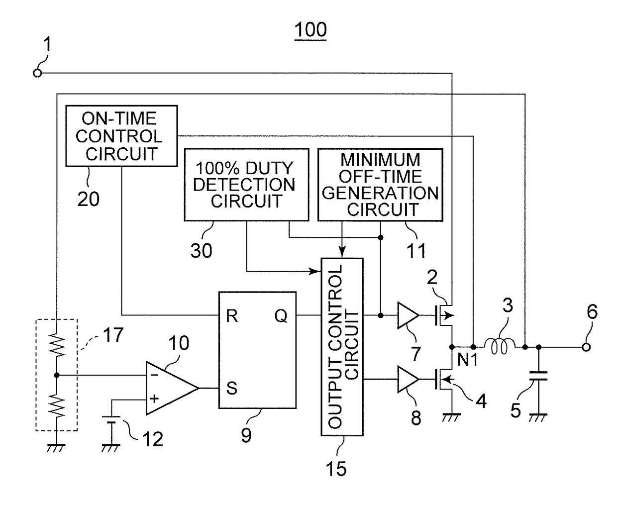
[0028]FIG. 1 is a circuit diagram of a switching regulator according to the present embodiment.

[0029]The switching regulator 100 according to the present embodiment is equipped with a feedback resistor 17, a reference voltage circuit 12, an error comparator 10, an R-S flip-flop circuit 9, an output control circuit 15, drivers 7 and 8, a PMOS transistor 2 which is a high-side switching element, an NMOS transistor 4 which is a low-side switching element, an on-time control circuit 20, a minimum off-time generation circuit 11, a 100% DUTY detection circuit 30, an inductor 3, and an output capacitor 5.

[0030]The feedback resistor 17 divides an output voltage Vout outputted from an output terminal 6 to generate a feedback voltage VFB. The reference voltage circuit 12 generates a reference voltage VREF. The error comparator 10 compares the feedback voltage VFB inp...


PUM


Abstract

To provide a COT-controlled switching regulator capable of preventing an output voltage from excessively exceeding a desired voltage even though a light load is connected to an output terminal. A switching regulator of the present invention is configured to be equipped with a 100% DUTY detection circuit which detects a 100% DUTY at which a high-side switching element continues an on state for a prescribed time or more and outputs a detected signal to an output control circuit and to cause the output control circuit to turn off the high-side switching element when the output control circuit receives the detected signal therein.

Description

RELATED APPLICATIONS[0001]This application claims priority under 35 U.S.C. §119 to Japanese Patent Application No. 2016-032102 filed on Feb. 23, 2016, the entire content of which is hereby incorporated by reference.BACKGROUND OF THE INVENTION[0002]Technical Field[0003]The present invention relates to a switching regulator which outputs a desired voltage from an output terminal.[0004]Background Art[0005]FIG. 6 is a circuit diagram illustrating a related art switching regulator.[0006]When the voltage of an output terminal 6 becomes lower than a prescribed voltage, and a feedback voltage VFB is lowered more than a reference voltage VREF, an error comparator 610 outputs an H signal. When the H signal is inputted to an input terminal S, an R-S flip-flop circuit 609 outputs the H signal from an output terminal Q. An output control circuit 615 turns on a PMOS transistor 602 and turns off an NMOS transistor 604 through drivers 607 and 608 respectively. In that state, the H signal is outputt...

Claims


Application Information

Patent Timeline
Patent Type & Authority Applications(United States)
IPC IPC(8): H02M3/157
CPCH02M3/157H02M3/1588H02M3/156Y02B70/10H02M1/0032H02M3/158H02M1/08H02M1/14
Inventor KAWANO, AKIHIROGOTO, KATSUYA
Owner ABLIC INC
Why Eureka
Try Eureka