
Article Transport Facility

a technology for transporting facilities and articles, applied in the direction of mechanical conveyors, basic electric elements, load-engaging elements, etc., can solve the problems of reducing the operational efficiency of the article transport facility, difficult to flexibly set the height of the adjusting-purpose support surface p to correspond to the height of the actual support platform, and difficult to provide the adjusting-purpose support surface p with small distances between

Inactive Publication Date: 2017-08-31
DAIFUKU CO LTD
View PDF0 Cites 4 Cited by
  • Summary
  • Abstract
  • Description
  • Claims
  • Application Information

AI Technical Summary

Benefits of technology

The technology described in this patent allows for more flexible positioning of a support surface for adjusting a vehicle that transports articles. The support surface can be adjusted to different heights, which makes it easier to adapt to different article transport facilities. This also reduces the amount of calculations required to adjust the profile information, resulting in improved efficiency of the article transport facility. Overall, this technology provides a solution for more effectively adjusting the support surface and improving operational efficiency.

Problems solved by technology

When the adjusting is done using a support platform on which an article is actually placed, the support platform cannot be used while the adjusting is being done, which may reduce the operational efficiency of the article transport facility.
However, such a structure makes it difficult to flexibly set the height of the adjusting-purpose support surface P to correspond to the height of the actual support platform.
In addition, when the differences in the heights of different adjusting-purpose support surfaces P are small, any two support portions SSs that are adjacent each other along the vertical direction may interfere with each other so that the structure also makes it difficult to provide adjusting-purpose support surfaces P with small distances between them.

Method used


Image

  • Article Transport Facility
  • Article Transport Facility
  • Article Transport Facility

Examples


Embodiment Construction

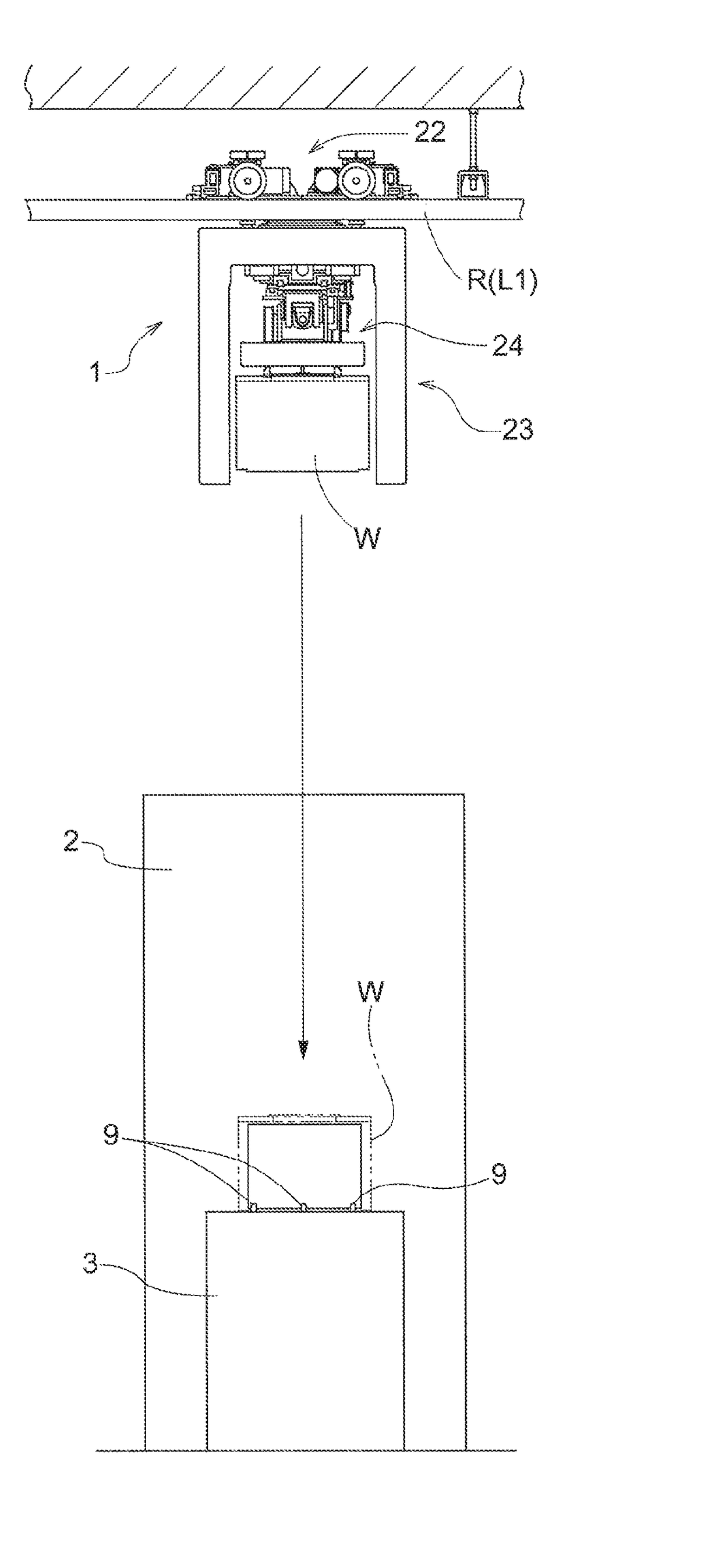
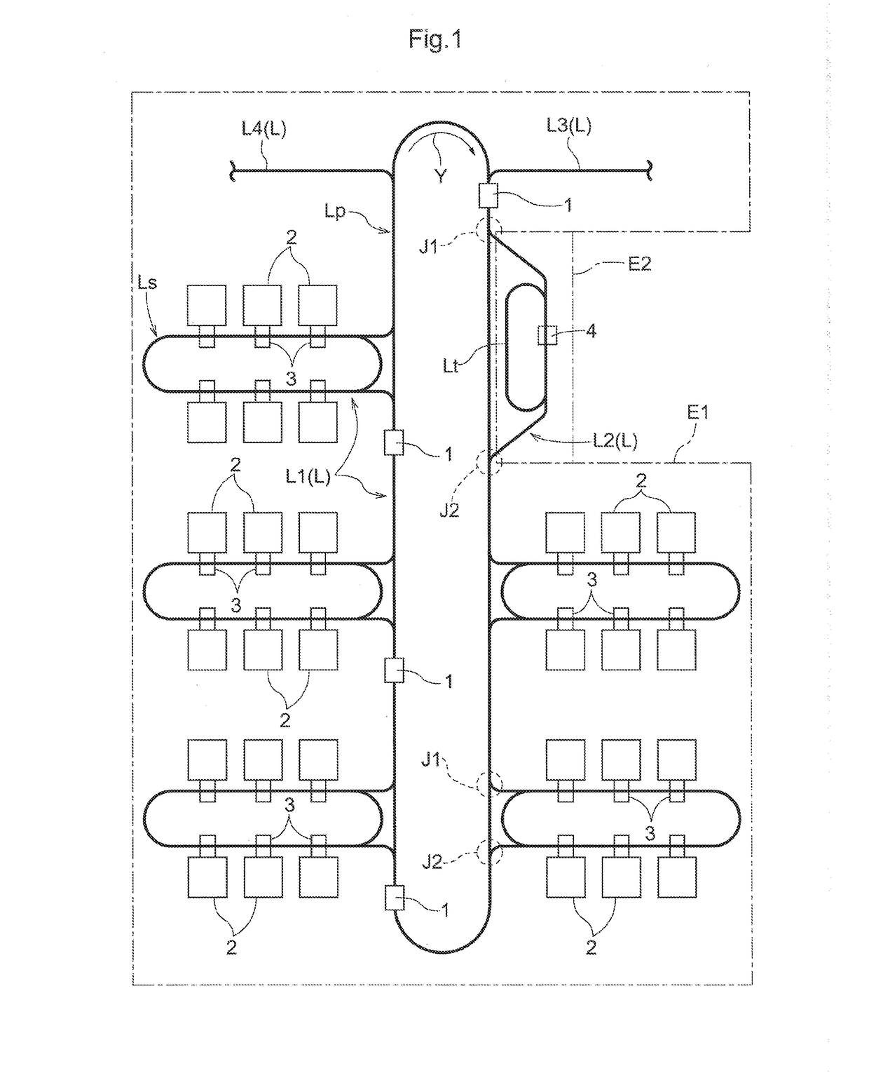
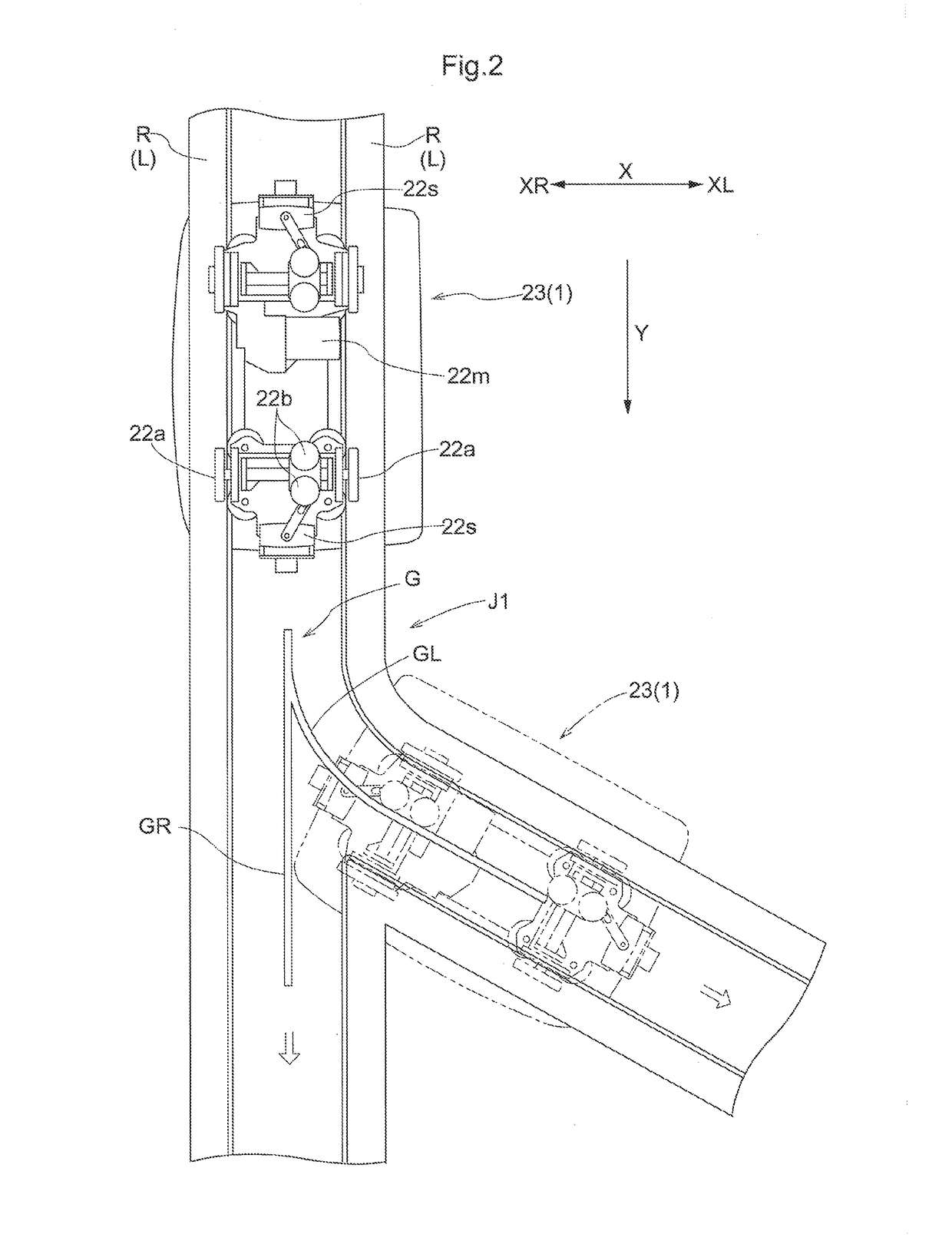
[0033]Embodiments of an article transport facility are described next with reference to the drawings. FIG. 1 schematically shows an example of an arrangement of an article transport facility. In the present embodiment, descriptions are given using an example in which the article transport facility includes article transport vehicles (ceiling or overhead transport vehicles 1) each of which travels in one direction along travel paths L to transport articles W, one at a time, between a plurality of semiconductor processing devices (processing devices 2) each of which performs one or more of various processes such as thin film formation or deposition, photo lithography, and etching, on semiconductor substrates. Each travel path L is formed or defined by travel rails R (see FIGS. 2 and 3) which are supported by support brackets and are installed on the ceiling side. The travel paths L includes branching portions J1 at each of which a path branches, or splits, off from a path and merging ...


PUM


Abstract

An article transport facility includes an article transport vehicle which is suspended from and supported by one or more travel rails supported by a ceiling, and is configured to suspend and support an article, and to transport the article from a support platform that serves as a transport origin to another support platform that serves as a transport destination. This article transport facility has an adjusting-purpose support platform which includes an adjusting-purpose support surface on which an adjusting-purpose device, which is used for a purpose of adjusting transporting-purpose profile information, can be placed in the same manner in which an article is placed on a support platform. The adjusting-purpose support surface is capable of being moved such that a height thereof can be varied continuously between an upper limit height and a lower limit height specified in advance.

Description

CROSS-REFERENCE TO RELATED APPLICATION[0001]This application claims priority to Japanese Patent Application No. 2016-037786 filed Feb. 29, 2016, the disclosure of which is hereby incorporated in its entirety by reference.FIELD OF THE INVENTION[0002]The present invention relates to an article transport facility includes an article transport vehicle which is configured to travel while being suspended from and supported by one or more travel rails supported by a ceiling, and is configured to suspend and support an article, and to transport the article from a support platform that serves as a transport origin to another support platform that serves as a transport destination.BACKGROUND ART[0003]The article transport faculties have been in use in which articles are automatically transported by means of article transport vehicles suspended from rails provided to the ceiling. In order to transfer an article with high accuracy, or more specifically, in order to accurately hold an article at...

Claims


Application Information

Patent Timeline
IPC IPC(8): B65G19/02B66C1/00
CPCB66C1/00B65G19/025B65G35/06B65G43/00B66C9/00B66C13/16H01L21/67706H01L21/67724H01L21/67733H01L21/6773H01L21/67751H01L21/67757B65G49/061B65G2201/0297
Inventor HORII, TAKAHIROWADA, YOSHINARI
Owner DAIFUKU CO LTD
Learn More