Stator of planar type motor, and planar type motor using same

a planar type, planar type technology, applied in the direction of windings, magnetic circuits characterised by magnetic materials, magnetic circuit shapes/forms/constructions, etc., can solve the problems of high core loss, degraded magnetic properties, increased manufacturing costs, etc., to achieve easy manufacturing, reduce torque ripples, and maximize the effect of performan

Active Publication Date: 2017-08-31
KOREA ELECTRONICS TECH INST
View PDF4 Cites 10 Cited by
  • Summary
  • Abstract
  • Description
  • Claims
  • Application Information

AI Technical Summary

Benefits of technology

[0016]A planar type motor according to the present invention is easy to manufacture and performance thereof can be maximized by a first core, which is difficult to form by stacking electric steel plates, being formed of a soft magnetic powder, and arranging a second core, which is formed by stacking electric steel plates having the same size, at a region in which an eddy current is concentrated.
[0017]In addition, since a first core and a second core are not integrally formed with a support plate and coils are wound around a plurality of first cores and second cores and assembled on the support plate in a planar type motor according to the present invention, separate spaces are not needed for winding the coils, and thus, spaces between adjacent first cores are minimized and torque ripples can be reduced.

Problems solved by technology

Because of this, since a process in which molds corresponding to shapes of silicon steel plates are manufactured, silicon steel plates having the same size are stacked and cut, or the like is needed for molding silicon steel plates having different sizes, a manufacturing process is complex, and thus, there is a problem in that a manufacturing cost is increased.
However, when an integrated core extruded using a soft magnetic powder is used, there is an advantage in that manufacturing is easy, but a high core loss occurs compared to a core formed by stacking electric steel plates, and thus, there is a problem in that magnetic properties are degraded.

Method used


Image

  • Stator of planar type motor, and planar type motor using same
  • Stator of planar type motor, and planar type motor using same
  • Stator of planar type motor, and planar type motor using same

Examples


first embodiment

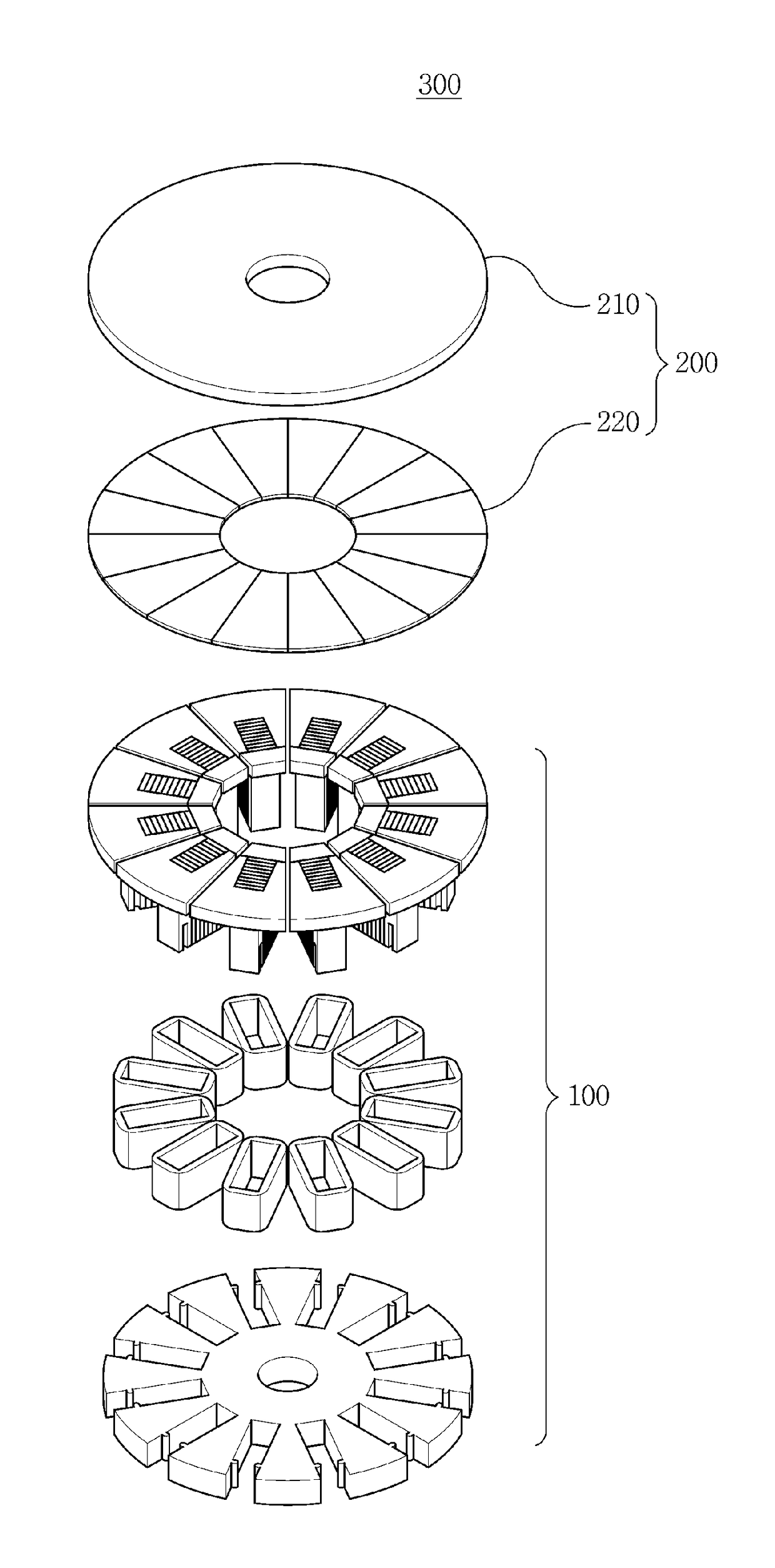
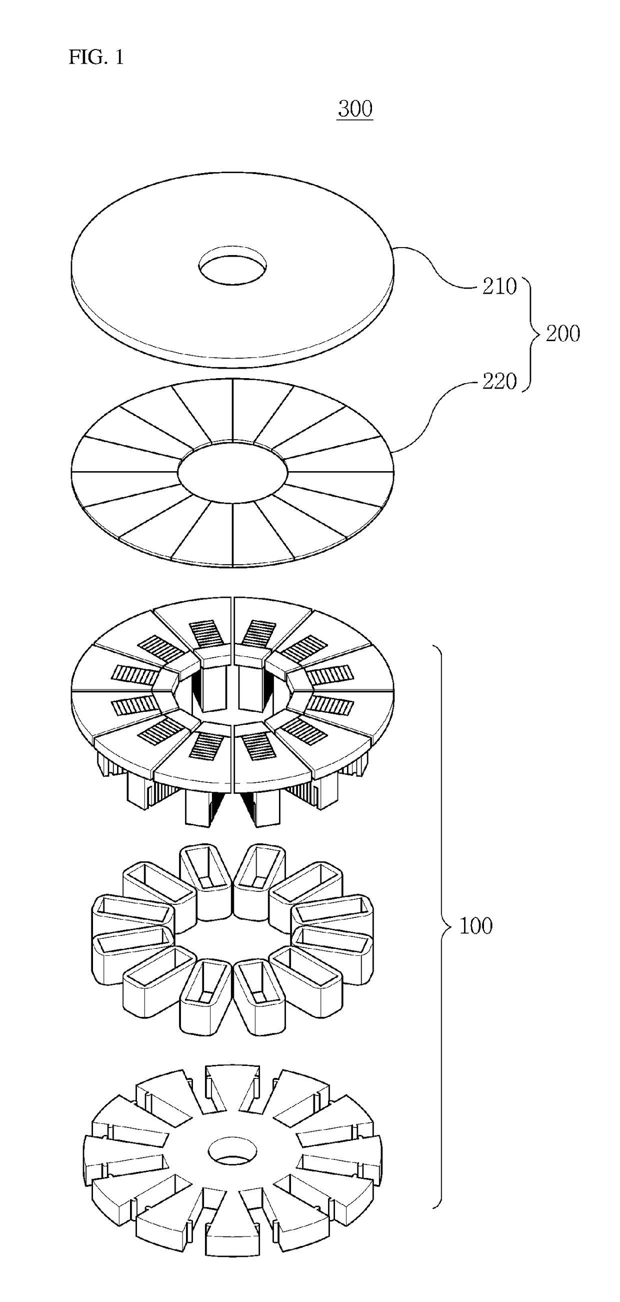
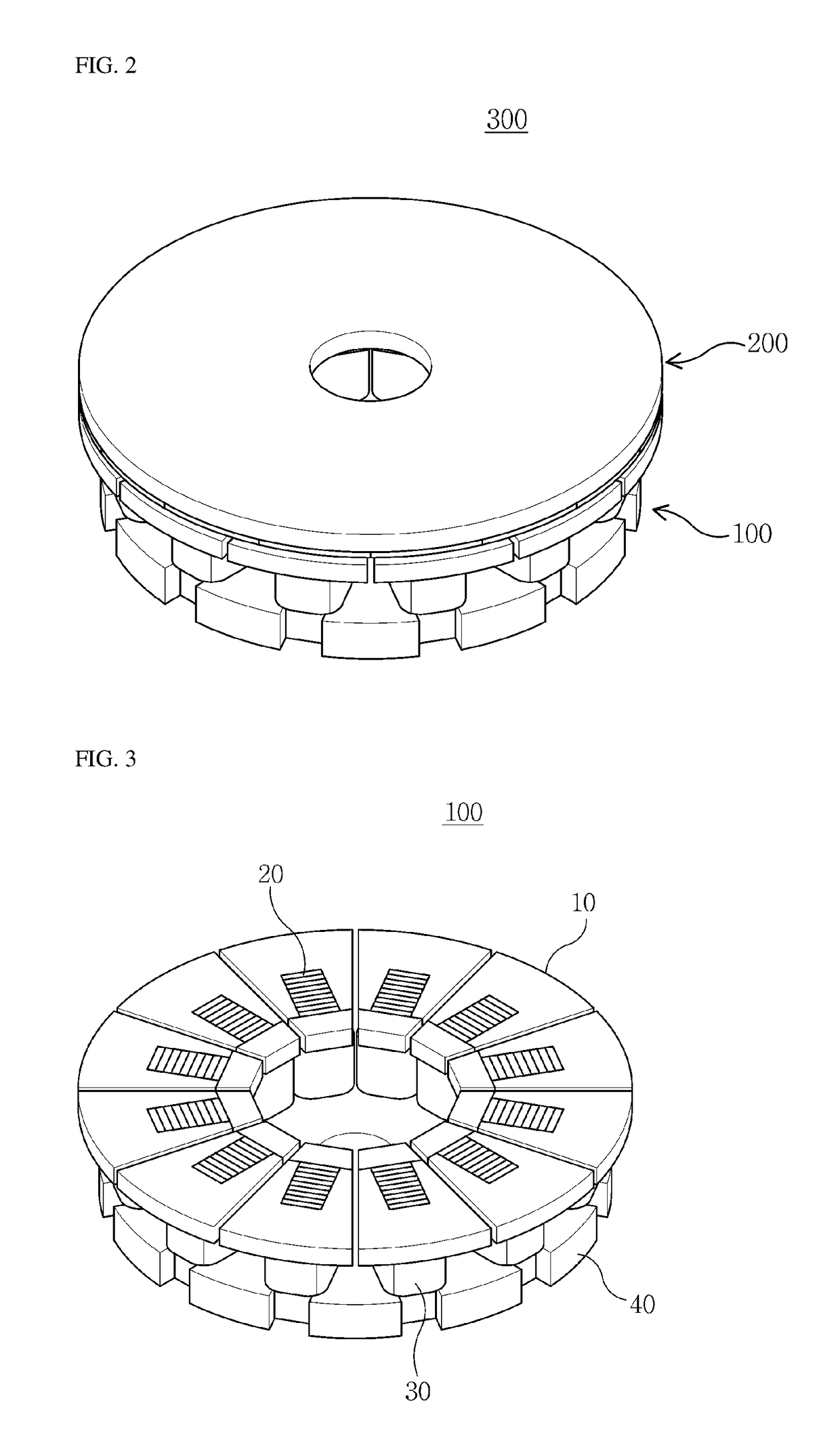
[0032]Referring to FIGS. 1 and 2, a planar type motor 300 according to the present invention includes a stator 100 and a rotor 200 provided to be rotatable with respect to the stator 100. The rotor 200 includes a second support plate 210 and permanent magnets 220 spaced apart from the stator and provided on one surface of the second support plate 210 facing the stator 100.

[0033]The planar type motor 300 is operated by the rotor 200, which is provided to rotate in a state in which a predetermined gap is formed between the rotor 200 and the stator 100, by a repulsive or attractive force being generated between the stator 100 and the permanent magnets 220 of the rotor 200 to generate rotational torque by changing a direction of a current flowing through the stator 100.

[0034]Hereinafter, the stator 100 according to the first embodiment of the present invention will be described in more detail.

[0035]FIG. 3 is an assembled perspective view illustrating the stator of the planar type motor ...

second embodiment

[0060]Hereinafter, a structure of a support plate 50 of a stator according to the present invention will be described.

[0061]Meanwhile, another embodiment, which will be described below, has substantially the same components as the first embodiment. Accordingly, the same components will not be repeatedly described, and thus, the same reference numerals and names will be assigned to the same components.

[0062]FIG. 6 is a perspective view illustrating a structure of the support plate of the stator according to the second embodiment of the present invention.

[0063]Referring to FIGS. 1 to FIG. 6, the support plate 50 of the stator according to the second embodiment of the present invention further includes a shaft system 51 which protrudes from a center of the support plate 50 in a direction perpendicular thereto.

[0064]The shaft system 51 may have a cylindrical shape perpendicularly extending from the center of the support plate 50, and a shaft may be inserted into the shaft system 51. The...

third embodiment

[0066]Hereinafter, a structure of a planar type motor 400 according to the present invention will be described.

[0067]FIG. 7 is an exploded perspective view illustrating the planar type motor according to the third embodiment of the present invention, and FIG. 8 is an assembled perspective view illustrating the planar type motor according to the third embodiment of the present invention.

[0068]Referring to FIGS. 7 and 8, the planar type motor 400 according to the third embodiment of the present invention may include a plurality of stators 100-1 and 100-2 and a plurality of rotors 200-1 and 200-2 in order to correspond to each other.

[0069]Here, the plurality of rotors 200-1 and 200-2 are positioned at an outermost portion, and the stators 100-1 and 100-2 may be positioned between the rotors 200-1 and 200-2. Here, adjacent stators 100-1 and 100-2 commonly use one support plate 40, and first cores 10 and second cores 20 may be inserted into both side surfaces of the support plate 40.

[007...


PUM


Abstract

The described technology relates to a stator of a planar type motor and a planar type motor using the same, which are easy to manufacture and are capable of reducing core losses, thereby maximizing motor performance. First cores that are difficult to form by stacking electrical steel plates are formed of soft magnetic powders, and second cores that are formed by stacking electrical steel plates having the same size are arranged in a region where a vortex is concentrated, thereby allowing easy manufacture and being capable of maximizing the performance of the planar type motor.

Description

TECHNICAL FIELD[0001]The present invention relates to a planar type motor, and more particularly, to a stator of a planar type motor which is used for driving an electric vehicle, a washer, and the like, and a planar type motor using the stator.BACKGROUND ART[0002]A planar type motor includes a stator configured to generate a magnetic field and a rotor provided to rotate with respect to the stator. The stator includes a plurality of cores which are disposed to have a predetermined distance therebetween in a circumferential direction thereof and protrude to a predetermined height in a direction of a shaft, and the cores are coupled to grooves formed in a stator body in the direction of the shaft. The rotor includes permanent magnets arranged to have a predetermined distance therebetween in a circumferential direction thereof and is provided to rotate in a state in which a predetermined gap is formed between the rotor and the stator. The planar type motor generates a repulsive or attr...

Claims


Application Information

Patent Timeline
Patent Type & Authority Applications(United States)
IPC IPC(8): H02K1/17H02K37/08H02K1/18
CPCH02K1/17H02K1/187H02K37/08H02K1/02H02K41/031H02K3/525H02K1/12H02K1/148H02K3/522H02K21/24H02K1/182
Inventor RHYU, SEHYUNKIM, YOUNGKYOUNSEO, JUNGMOOLEE, JEONGJONGJUNG, INSOUNG
Owner KOREA ELECTRONICS TECH INST
Why Eureka
Try Eureka