Supercharge Your Innovation With Domain-Expert AI Agents!

Method and device for ascertaining an image of the surroundings of a vehicle

a vehicle and surroundings technology, applied in the field of vehicle surroundings ascertaining, can solve the problems of systematic 3d reconstruction errors, complex computation methods, and inability to efficiently implement embedded camera systems, and achieve the effects of simple ascertaining, precise compensation of location, and simple implementation

Active Publication Date: 2017-08-31
ROBERT BOSCH GMBH
View PDF3 Cites 4 Cited by
  • Summary
  • Abstract
  • Description
  • Claims
  • Application Information

AI Technical Summary

Benefits of technology

The patent text presents a method and device for creating an image of the surroundings of a vehicle by using vehicle parameters and driving parameters to compensate for errors caused by time-offset partial images. This approach offers the advantage of using a cost-effective and technically simple image recording sensor, while compensating for errors during the evaluation of an image using vehicle parameters and driving parameters. The technical effects of this invention are a more accurate and reliable image of the vehicle's surroundings, which can be used for additional driver assistance systems of the vehicle.

Problems solved by technology

This is generally not taken into consideration, however, when using SfM algorithms for the 3D scene reconstruction, from which systematic 3D reconstruction errors result.
More complex approaches avoid the inclusion of a priori assumptions about the scene geometry by employing complex computation methods (bundle adjustment), which cannot be efficiently implemented in embedded camera systems (for example, a camera for driver assistance systems in the motor vehicle).

Method used


Image

  • Method and device for ascertaining an image of the surroundings of a vehicle
  • Method and device for ascertaining an image of the surroundings of a vehicle
  • Method and device for ascertaining an image of the surroundings of a vehicle

Examples


Embodiment Construction

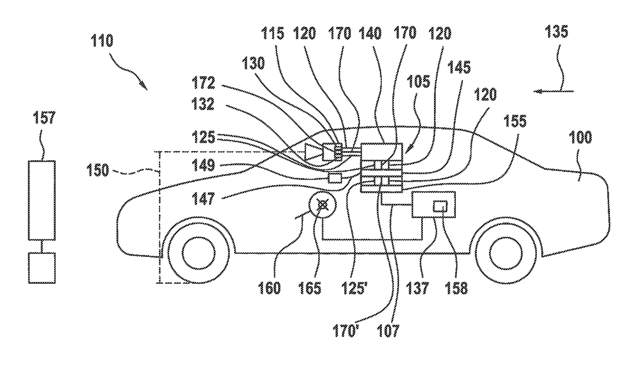
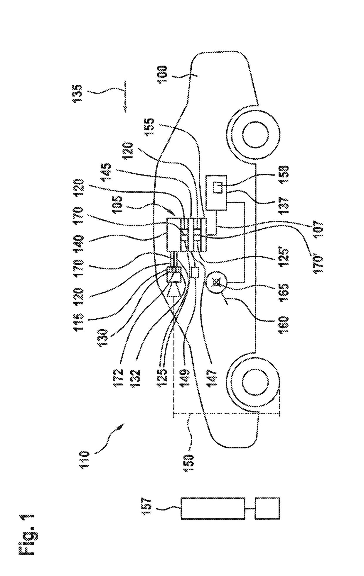
[0038]FIG. 1 shows a block diagram of a vehicle 100, including one exemplary embodiment of a device 105 for ascertaining an image 107 of surroundings 110 of a vehicle 100. Vehicle 100 also includes a camera 115 as a visual image sensor, camera 115 being configured to provide first image data 120 and second image data 125. First image data 120 are provided by a first image recording area 130, whereas second image data 125 are provided by a second image recording area 132 of camera 115. Image recording areas 130 and 132 are different subsections of an image capture sensor of camera 115 and may portray different sections or viewing angles of camera 115 of surroundings 110 pictorially in image 107. In cost-efficient cameras 115, which may be intended for use in the approach presented herein, first image data 120 are also provided earlier than second image data 125. If vehicle 100 then travels at driving speed 135, second image data 125 are recorded from another perspective of camera 115...


PUM


Abstract

A method for ascertaining an image of the surroundings of a vehicle. The method includes reading in first image data and at least second image data, the first image data representing image data of a first image recording area of a camera in or on a vehicle and the second image data representing image data from a second image recording area of the camera differing from the first image recording area, and the second image data having been recorded chronologically after the first image data. The method further includes processing the second image data using a vehicle parameter and / or driving parameter, to obtain processed second image data. Finally, the method includes combining the first image data with the processed second image data to obtain the image of the surroundings of the vehicle.

Description

RELATED APPLICATION INFORMATION[0001]The present application claims priority to and the benefit of German patent application no. 10 2016 202 948.7, which was filed in Germany on Feb. 25, 2016, the disclosure of which is incorporated herein by reference.FIELD OF THE INVENTION[0002]The present invention is directed to a method or a device according to the definition of the species in the independent claims. The subject matter of the present invention is also a computer program.BACKGROUND INFORMATION[0003]Methods are known from the related art with respect to 3D reconstruction using rolling shutter cameras (C. Geyer, M. Meingast, and S. Sastry. Geometric models of rolling shutter cameras. In Proc. 6th OmniVis WS, 2005 and G. Klein and D. Murray. Parallel tracking and mapping on a camera phone. In Proc. ISMAR '09, Orlando, October 2009), which compensate for the influence of the rolling shutter under the assumption of a known 3D geometry of the objects to be reconstructed (for example, ...

Claims


Application Information

Patent Timeline
Patent Type & Authority Applications(United States)
IPC IPC(8): H04N13/02H04N5/353G06T7/00G06T7/70G06T11/60G06T7/20H04N13/00G06K9/00H04N13/221
CPCH04N13/0221H04N13/0018H04N13/004H04N5/3532G06K9/00791G06T2207/30268G06T11/60G06T7/20G06T7/97H04N2013/0085G06T7/70G01B11/24G01C11/08H04N13/221G06V20/56H04N25/60G06T2207/30252G06T7/579H04N25/531H04N7/183B60R2300/10H04N23/683H04N23/689H04N13/156
Inventor NIEHSEN, WOLFGANG
Owner ROBERT BOSCH GMBH
Features
  • R&D
  • Intellectual Property
  • Life Sciences
  • Materials
  • Tech Scout
  • Unparalleled Data Quality
  • Higher Quality Content
  • 60% Fewer Hallucinations
Learn More