Driven load-bearing system

a technology of load-bearing system and drive, which is applied in the direction of rigid containers, instruments, transportation and packaging, etc., can solve the problems of relative high cost and bulky devices, damage during alignment,

Active Publication Date: 2017-09-07
EIDELSON ARTHUR
View PDF5 Cites 22 Cited by
  • Summary
  • Abstract
  • Description
  • Claims
  • Application Information

AI Technical Summary

Benefits of technology

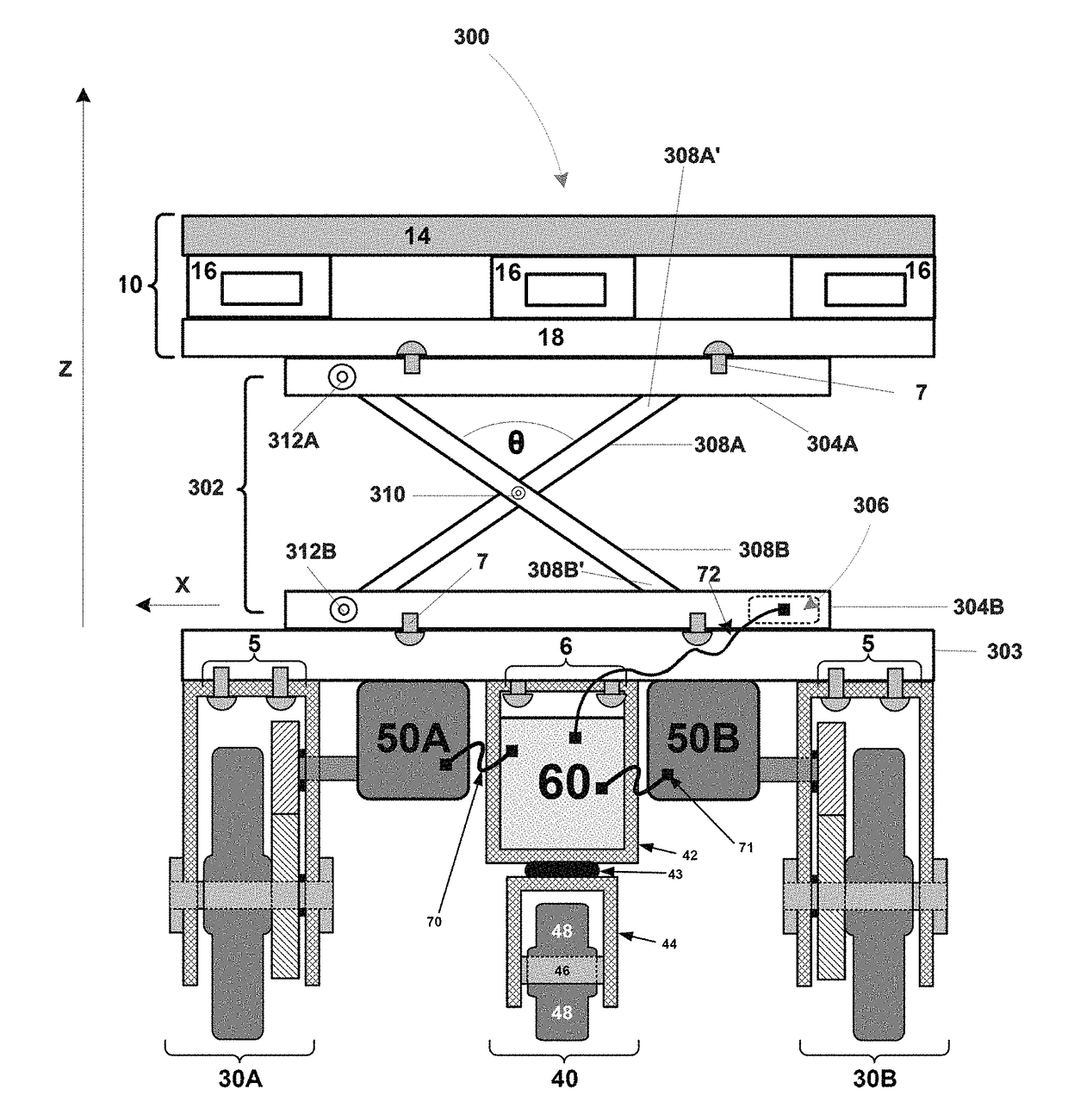
[0014]A device for supporting and moving a load within an area may include: a motive construct configured to support the load and move the load to a ground location within the area; a lift mechanism coupled to the motive construct, the lift mechanism being configured to effect movement of the motive construct to a height relative to the ground location; and a remote controller operatively coupled to the device via at least one of a cable connection and a wireless connection, the remote controller being configured to steer the motive construct and / or to control the lift mechanism. The remote controller may be handheld. The lift mechanism may be a scissor lift. The device may further include a motor; and a transmission, the transmission operatively coupling the motor to the lift mechanism. The motor may include any suitable motor, which may be, for example, at least one of an electric motor, a combustion motor, a pneumatic motor, a magnet motor, and a hydraulic motor. The device may further include at least one control circuit configured to control steering of the motive construct and to control operation of the lift mechanism, the remote controller being operatively connected to the at least one control circuit. The remote controller may include at least one designated button for sending a signal related to at least one lift mechanism operation. The remote controller may include a plurality of control circuit components each of which transmits a discrete signal as a result of physical interaction between a hand-operated directional control and the plurality of control circuit components. The directional control may include a joystick, a switch, a key pad, a touch screen, a scrolling device, or an application running on a machine from the group consisting of computers, mobile devices, interactive displays, and combinations thereof. The device may further include at least one sensor operatively coupled to the motive construct, the sensor being configured to determine at least one characteristic of the load supported by the motive construct; and at least one brake configured to selectively inhibit movement of the motive construct.

Problems solved by technology

Present attempts to provide material transport mechanisms have resulted in relatively expensive and bulky devices that either grab or lift a load resting on a pallet along with the pallet itself.
For example, if the force is significant, the tines of a fork-lifting truck making contact with the lead boards of the pallet decks and / or connecting members of a pallet can cause damage during alignment.

Method used


Image

  • Driven load-bearing system
  • Driven load-bearing system
  • Driven load-bearing system

Examples


Embodiment Construction

[0045]As required, a detailed illustrative embodiment of the present disclosure is disclosed herein. However, techniques, systems, compositions and operating structures in accordance with the present disclosure may be embodied in a wide variety of sizes, shapes, forms and modes, some of which may be quite different from those in the disclosed embodiment. Consequently, the specific structural and functional details disclosed herein are merely representative, yet in that regard, they are deemed to afford the best embodiment for purposes of disclosure and to provide a basis for the claims herein, which define the scope of the present invention.

[0046]Reference will now be made in detail to several embodiments of the invention that are illustrated in the accompanying drawings. Wherever possible, same or similar reference numerals are used in the drawings and the description to refer to the same or like parts or steps. The drawings are in simplified form and are not to precise scale. For ...


PUM

PropertyMeasurementUnit
sizeaaaaaaaaaa
sizeaaaaaaaaaa
sizeaaaaaaaaaa

Abstract

A device for supporting and moving a load within an area may include a motive construct configured to support the load and move the load to a ground location within the area; a lift mechanism coupled to the motive construct, the lift mechanism being configured to effect movement of the motive construct to a height relative to the ground location; and a remote controller operatively coupled to the device via at least one of a cable connection and a wireless connection, the remote controller being configured to steer the motive construct and/or to control the lift mechanism. The device may further include at least one sensor to detect a characteristic of the load. The device may further include a braking system.

Description

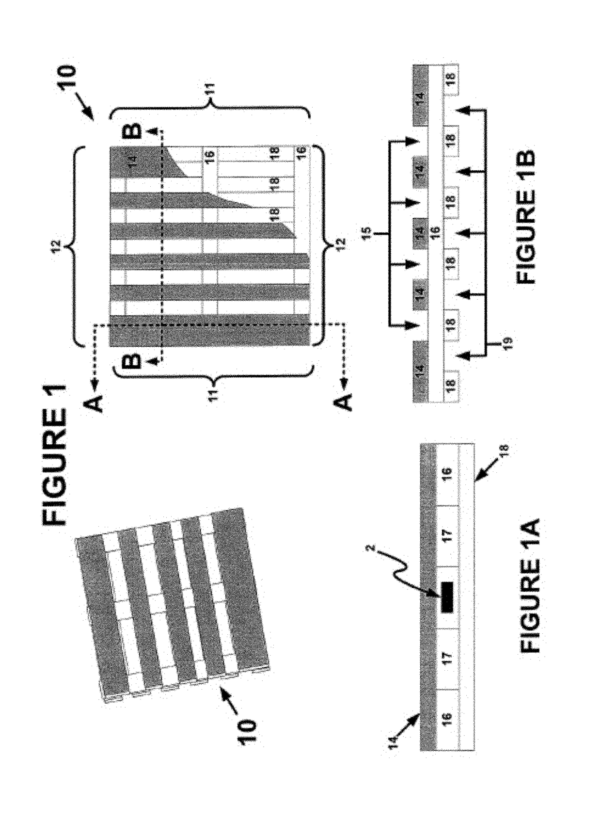
CROSS REFERENCE TO RELATED APPLICATIONS[0001]The present application is a continuation-in-part of co-pending U.S. patent application Ser. No. 14 / 614,285 filed Feb. 4, 2015, which is a continuation of U.S. patent application Ser. No. 13 / 804,015, which was filed Mar. 14, 2103 and is now U.S. Pat. No. 8,983,740, the entire contents of each of which is hereby incorporated herein by reference.FIGURE SELECTED FOR PUBLICATION[0002]FIG. 12BACKGROUND[0003]Technical Field[0004]The present disclosure relates to driven, load bearing systems and methods for constructing and using the same to move objects placed or stored thereon.[0005]Description of the Related Art[0006]Constructs, such as pallets and skids, which may be used for the support, storage, and transportation of materials, are in widespread usage. The most common types of pallets are constructed from wood, plastic, metal, or paper. Some pallets contain two decks made up from a plurality of longitudinally and laterally extending cross-...

Claims


Application Information

Patent Timeline
Patent Type & Authority Applications(United States)
IPC IPC(8): B62D51/00B65D19/42G08C17/02B66F9/20B66F9/06B23P6/00G08C23/00
CPCB23P6/00B62D51/001B65D19/42G08C17/02G08C23/00B66F9/20B66F9/063Y10T29/49716B62D61/04B62D63/02G08C2201/71G08C2201/93
Inventor EIDELSON, ARTHUR
Owner EIDELSON ARTHUR
Why Eureka
Try Eureka