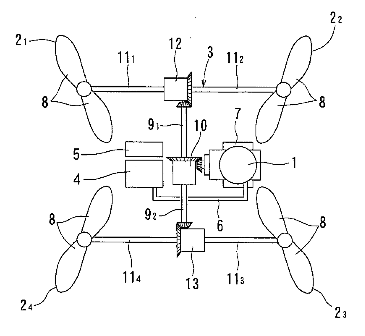
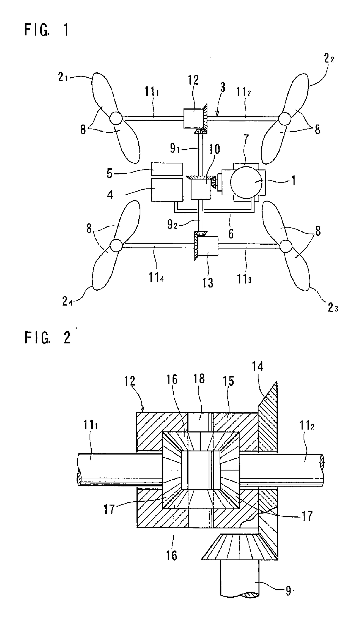
Multicopter
- Summary
- Abstract
- Description
- Claims
- Application Information
AI Technical Summary
Benefits of technology
Problems solved by technology
Method used
Image

Examples
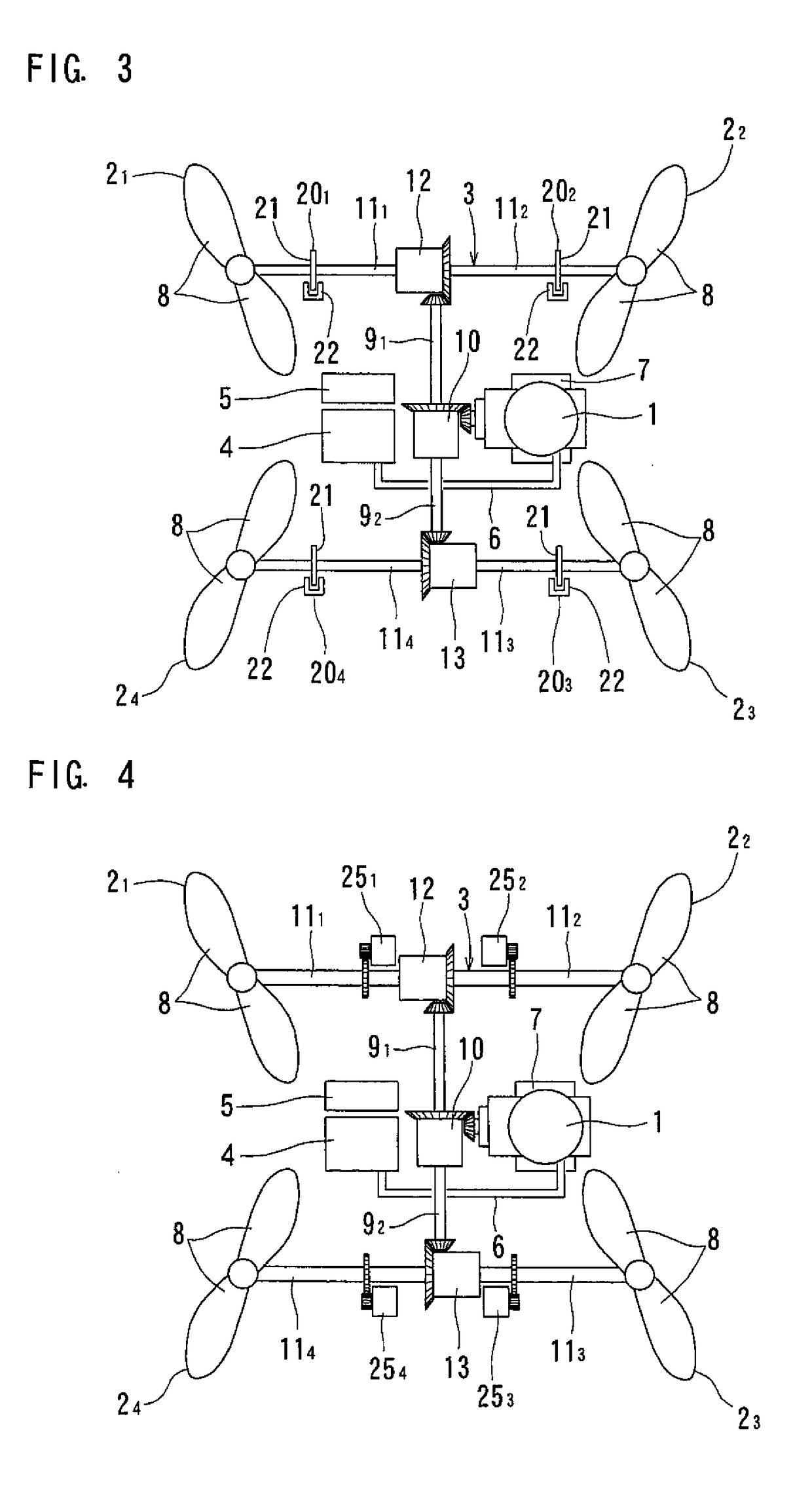
second embodiment
[0064]The rotation transmission path 3 of the second embodiment includes first to fourth brake devices 201, 202, 203 and 204 which apply braking forces to the first to fourth shafts 111, 112, 113 and 114, respectively. The first to fourth brake devices 201, 202, 203 and 204 are non-contact type brake devices each comprising a brake disk 21 that rotates together with the corresponding one of the first to fourth shafts 111, 112, 113 and 114, and a stator 22 configured to apply a braking force to the brake disk 21, while being kept out of contact with the brake disk 21. For example, the brake devices may be eddy current disk brakes.
[0065]With the multicopter of the second embodiment, it is possible to apply different rotational resistances to the first to fourth shafts 111, 112, 113 and 114, respectively, which are connected together via the differentials 10, 12 and 13, by selectively and individually actuating the first to fourth brake devices 201, 202, 203 and 204, thereby rotating t...
third embodiment
[0071]Since the multicopter of the third embodiment uses regenerative braking devices as the first to fourth brake devices 251, 252, 253 and 254, the electric power generated by the brake devices 251, 252, 253 and 254 is recyclable, which minimizes energy loss, thus effectively prolonging the flight duration of the multicopter.
[0072]FIG. 5 shows a multicopter of the fourth embodiment according to the present invention. Here, elements corresponding to those of the second embodiment are denoted by identical numerals, and their description is omitted.
[0073]The rotation transmission path 3 of this embodiment includes first to fourth auxiliary motors 231, 232, 233 and 234 which apply torques to the first to fourth shafts 111, 112, 113 and 114, respectively. The rotation transmission path 3 further includes a one-way clutch 24 disposed between the first auxiliary motor 231 and the first shaft 111 such that the one-way clutch 24 allows transmission of torque that tends to accelerate the ro...
fourth embodiment
[0076]Since the multicopter of the fourth embodiment is configured such that the first to fourth shafts 111, 112, 113 and 114 are rotated at different speeds by applying torques to the first to fourth shafts 111, 112, 113 and 114, energy loss is small compared to the arrangement in which the rotational speeds of the first to fourth shafts 111, 112, 113 and 114 are controlled by applying braking forces thereto, so that it is possible to effectively prolong the flight duration of the multicopter.
[0077]While the multicopter of each of the above-described embodiments uses a single engine 1, two engines 1 may be used, as shown in FIG. 6, so that the rotations of the two engines 1 are applied simultaneously to the (single) center differential 10. With this arrangement, redundancy of the multicopter improves because even if one of the two engines 1 unexpectedly stops, the propellers 21, 22, 23 and 24 can still be driven by the other engine.
[0078]While the multicopter of each of the above-d...
PUM
 Abstract
Description
Claims
Application Information