System and method for arresting and neutralizing unmanned vehicles

a technology for unmanned vehicles and arresting systems, applied in special-purpose vessels, weapons, transportation and packaging, etc., can solve the problems of not offering all-encompassing solutions, the possibility of a larger collective threat, and the possibility of improvised threats never been higher

Active Publication Date: 2017-09-07
THE UNITED STATES OF AMERICA AS REPRESETNED BY THE SEC OF THE AIR FORCE
View PDF12 Cites 45 Cited by
  • Summary
  • Abstract
  • Description
  • Claims
  • Application Information

AI Technical Summary

Benefits of technology

[0015]Briefly stated, the present invention achieves these and other objects through the use of shielded material in a deployable vehicle arresting and containment device that, when used for the interception of an unmanned vehicle, effectively achieves RF isolation of that vehicle, breaking all external communications with that vehicle. The arresting and containment device, which may have internal and external antennas, could enable a variety of advanced effects such as localized GPS and command and control link spoofing and jamming as well as providing a vehicle for signal intercept and intelligence solutions. Additionally, due to the shielding properties of the arresting and containment device, semi-destructive means such as localized EMPs could be used to damage the encapsulated unmanned vehicle electronics.

Problems solved by technology

With the widespread commercial availability of unmanned vehicles (both remote controlled and autonomous), a potential for improvised threats has never been higher.
Swarm technology, that uses multiple vehicles working in conjunction with each other, produces the possibility of an even larger collective threat.
There have been numerous attempts at various techniques for detecting drone threats and mitigating those threats, but none of them offer all-encompassing solutions.
Currently proposed and existing systems fall short of offering layered solutions that cover the taxonomy of potential unmanned vehicle threats.
They often amount to destroying the vehicles with superior firepower—something not appropriate for domestic use due to concerns over collateral damage, or capturing the vehicle with a simplistic net, which does little to mitigate the risks associated with using the vehicles for surveillance or arming them to be remotely activated threats.
Using destructive force to eliminate an unmanned aerial vehicle (UAV) or “drone” threat can create a serious problem due to falling debris and collateral damage.
On the other hand, simple interference methods do not mitigate the threat posed by drones that navigate to pre-defined waypoints.
The only interference-based way to achieve the latter would be to transmit signals that interfere with GPS, however the FCC prohibits interference with approved devices as it can create other high level risks to public safety.
While the apparatus disclosed in U.S. Pat. No. 9085362 B1 creates a non-destructive means for UAV mitigation, it fails to mitigate threats from a UAV that might be equipped with self destructive features that could potentially be triggered by remote control via wireless signals or autonomously based on reaching a given GPS waypoint.
Such a destructive force could not only still enable the payload to be triggered, but may result in the damage or destruction of the capturing aircraft as well.
U.S. Pat. No. 9085362 B1 additionally falls short of providing a solution that could enable signal intelligence and reconnaissance on a captured UAV if it somehow fell out of the capture net.
While U.S. Pat. No. 9085362 B1 is non-destructive, it fails to provide a means for cyber and electronic countermeasures which could be used to target specific systems of the vehicle with destructive effects.
Finally, U.S. Pat. No. 9085362 B1 fails to address threats posed by non-airborne vehicles such as small RC cars and / or boats.

Method used


Image

  • System and method for arresting and neutralizing unmanned vehicles
  • System and method for arresting and neutralizing unmanned vehicles
  • System and method for arresting and neutralizing unmanned vehicles

Examples


Embodiment Construction

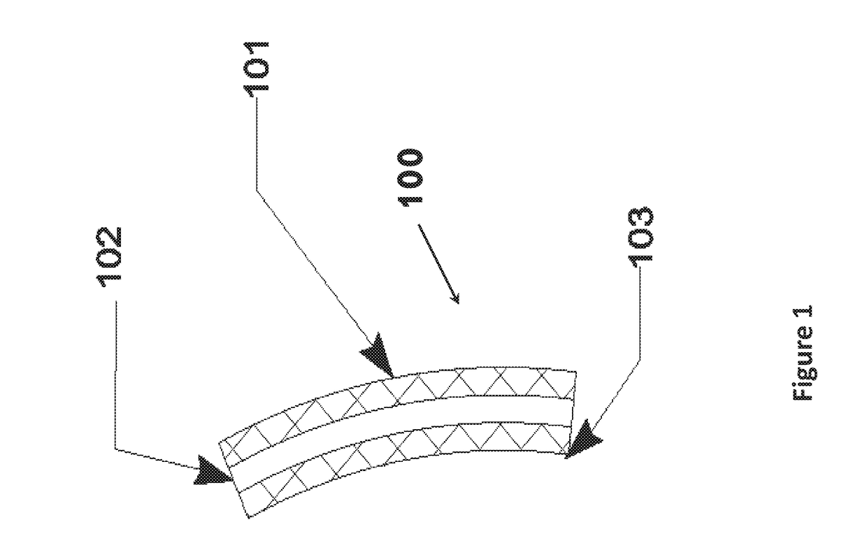
[0027]Referring to FIG. 1, a cross section of the construction of an exemplary embodiment of the RF Isolating Containment Unit (hereinafter RF ICU) 100 of the present invention is depicted. A layer of suitable conductive material 101 shields radio frequency signals from propagating in or out of the enclosed RF ICU 100. Additional layers of suitable supportive materials 102 that may have radio frequency absorptive properties and suitable conductive materials 103 may be added to increase the physical strength of the RF ICU 100 and increase the attenuation of radio frequency signals passing through it.

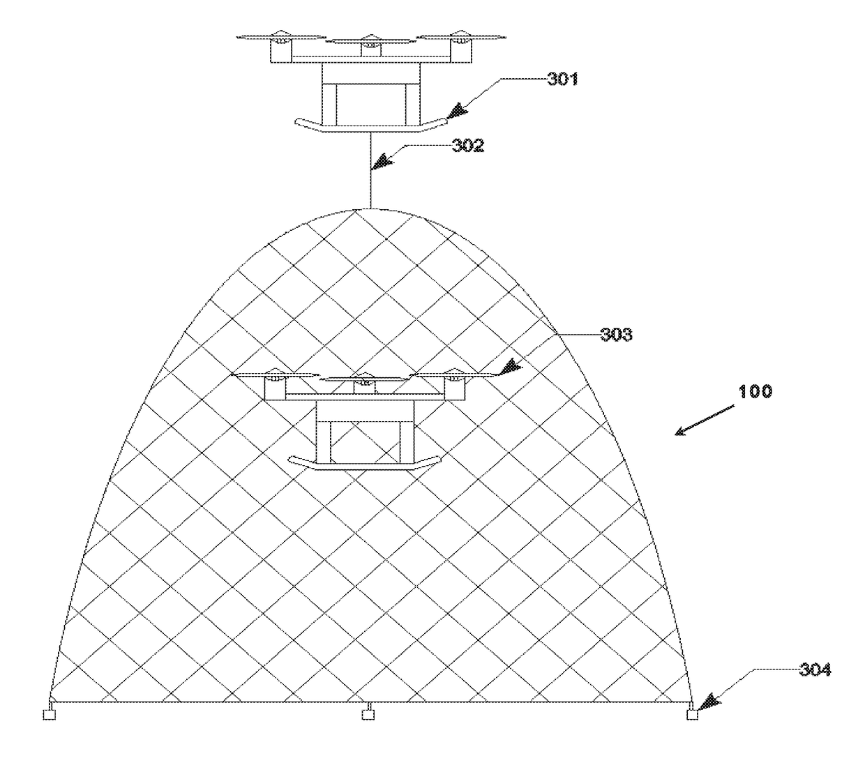
[0028]This embodiment of the present invention provides adequate radio frequency shielding and physical strength to achieve its two primary goals: capture a target unmanned aerial vehicle, and to drastically reduce the probability of reception of any outside radio frequency signals. Reducing the reception of outside radio frequency signals aids in the prevention of remote detonation of th...


PUM


Abstract

The use of shielded material in a deployable vehicle arresting and containment device that, when used for the interception of an unmanned vehicle, effectively achieves RF isolation of that vehicle, breaking all external communications with that vehicle. This apparatus, which may have internal and external antennas, could enable a variety of advanced effects such as localized GPS and command and control link spoofing and jamming as well as providing a vehicle for signal intercept and intelligence solutions. Additionally, due to the shielding properties of the arresting and containment device, semi-destructive means such as localized EMPs could be used to damage the encapsulated unmanned vehicle electronics.

Description

PRIORITY CLAIM UNDER 35 U.S.C. §119(e)[0001]This patent application claims the priority benefit of the filing date of provisional application Ser. No. 62 / 302,863 having been filed in the United States Patent and Trademark Office on Mar. 3, 2016 and now incorporated by reference herein.STATEMENT OF GOVERNMENT INTEREST[0002]The invention described herein may be manufactured and used by or for the Government for governmental purposes without the payment of any royalty thereon.BACKGROUND OF THE INVENTION[0003]This invention relates generally to unmanned vehicles and systems and methods for neutralizing them with a focus on capture apparatuses employing materials with radio frequency shielding properties so as to sever communications between a target vehicle and its operator, and enable a friendly operator's physical acquisition and command and control takeover of that vehicle.[0004]With the widespread commercial availability of unmanned vehicles (both remote controlled and autonomous), ...

Claims


Application Information

Patent Timeline
Patent Type & Authority Applications(United States)
IPC IPC(8): B64F1/02F41H13/00B62D63/04F41H11/02B64C39/02B63B35/00
CPCB64F1/02B64C39/024B63B35/00B64C2201/12F41H11/02F41H13/00B63B2035/006B62D63/04F41H7/005F41H13/0006H04K3/62H04K3/65H04K3/68H04K2203/22B64F1/027B64F1/0295B64U70/30
Inventor ASHDOWN, JONATHANSIKORA, PAULPOLAND, BRENDON
Owner THE UNITED STATES OF AMERICA AS REPRESETNED BY THE SEC OF THE AIR FORCE
Why Eureka
Try Eureka