Electronic Control Device

a technology of electronic control device and sealing structure, which is applied in the direction of electrical apparatus casings/cabinets/drawers, engine starters, etc., can solve the problems of high cost of silicone based adhesives or rubber packing, wide area for sealing, etc., and achieves the reduction of cost, size and weight of control units, and the effect of reducing the sealing material

Active Publication Date: 2017-09-07
HITACHI ASTEMO LTD
View PDF6 Cites 4 Cited by
  • Summary
  • Abstract
  • Description
  • Claims
  • Application Information

AI Technical Summary

Benefits of technology

[0011]According to the invention, a structure for reducing the seal material without reducing waterproof property is realized, by adopting a structure in which the sectional area of the seal material is changed. Decrease in the cost, the size and weight of the control unit and further improvement of the waterproof reliability can be realized.

Problems solved by technology

However, the silicone based adhesives or the rubber packing is a material with high cost, and wide area for sealing is required.

Method used


Image

  • Electronic Control Device
  • Electronic Control Device
  • Electronic Control Device

Examples


example 1

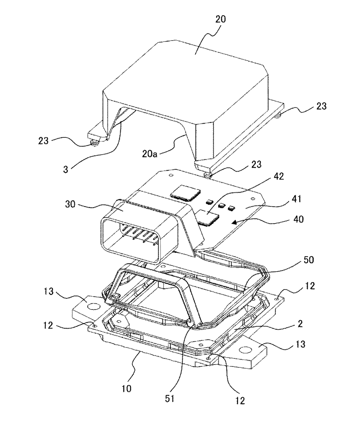
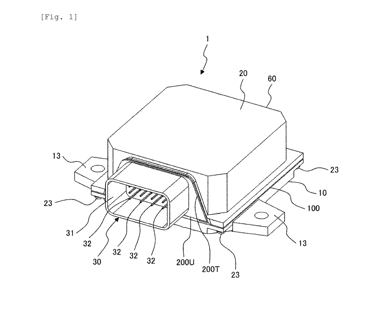
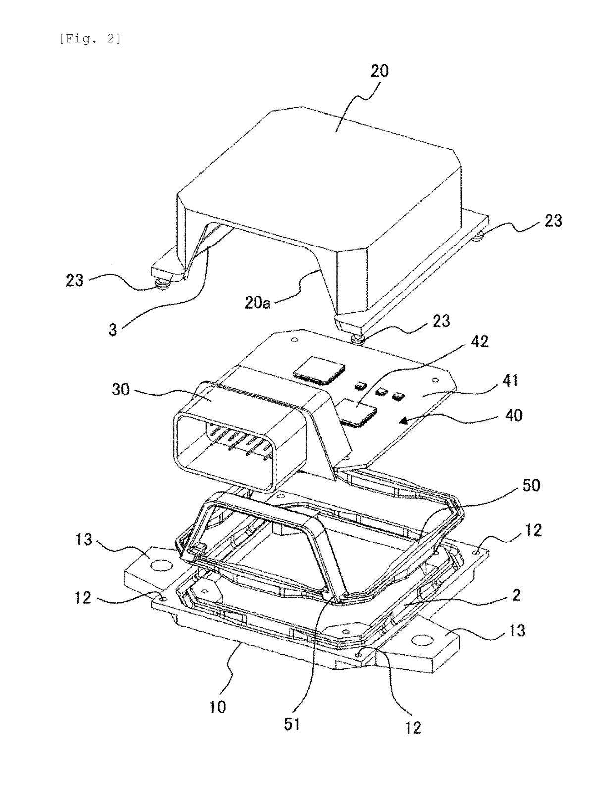
[0042]An example of the electronic control unit according to the invention will be described using FIG. 1 to FIG. 4. FIG. 1 is a perspective view illustrating an electronic control unit 1 according to the example. FIG. 2 is an exploded view illustrating the electronic control unit 1. FIG. 3 is a top view illustrating the electronic control unit 1. FIG. 4A, FIG. 4B, and FIG. 4C are partial cross-sectional views taken along line IVA-IVA, line IVB-IVB, and line IVC-IVC in FIG. 3. FIG. 1 to FIG. 3 are commonly used in Example 2 to Example 8.

[0043]The electronic control unit 1 includes a plurality of components (members) forming a space in an inside of the housing 60, and is configured by a base 10, a cover 20, and a connector 30, for example. In the following description, a vertical direction is defined based on FIG. 1. In other words, in the housing 60, a base 10 side is defined as a lower side, and a cover 20 side is defined as an upper side. In addition, for convenience, a surface in...

example 2

[0064]A second example according to the invention will be described using FIG. 5A, FIG. 5B, and FIG. 5C. FIG. 5A, FIG. 5B, and FIG. 5C are partial cross-sectional views illustrating cross sections taken along line IVA-IVA, line IVB-IVB, and line IVC-IVC in FIG. 3, as in FIG. 4A, FIG. 4B and FIG. 4C.

[0065]In this example, in order to make the seal sectional area at a position which is close to the fixing portions 12 and 23 smaller than the seal sectional area at a position which is away from the fixing portions 12 and 23, the width of the ridge 3 in the vicinity of the fixing portion 12 and 23 of the cover 20 is increased, or the height of the ridge 3 therein is increased. Accordingly, the amount of the seal material 50 in the vicinity of the fixing portions can be reduced.

[0066]Specifically, in the seal structure 100C at a position which is closest to the fixing portions 12 and 23, the ridge width Wf is the largest among the three seal structures 100A, 100B, and 100C. In the seal st...

example 3

[0071]A third example of the present invention will be described with reference to FIG. 6A, FIG. 6B, and FIG. 6C. FIG. 6A, FIG. 6B, and FIG. 6C are partial cross-sectional views illustrating cross sections taken along line IVA-IVA, line IVB-IVB and line IVC-IVC in FIG. 3, as in FIG. 4A, FIG. 4B, and FIG. 4C.

[0072]In the joining structure between the base 10 and the cover 20, for example, a base joining surface 11 is provided at the joining portion of the base 10, and the cover 20 has a cover joining surface 21 facing the base joining surface 11 with a gap therebetween, and there is also a surface seal structure in which the base 10 and the cover 20 are joined by the seal material 50 being interposed therebetween. In other words, in this example, opposing surfaces facing each other (base joining surface 11 and cover joining surface 21) are configured in the joining portion between the base 10 and the cover 20, and the gap between the base joining surface 11 and the cover joining surf...


PUM


Abstract

The purpose of the present invention is to provide a control unit whereby the quantity of a seal material to be used can be reduced, while ensuring waterproof performance. This electronic control device is provided with: a housing, wherein a plurality of members are bonded, and a peripheral end portion thereof is configured from a plurality of sides; a circuit board housed in the housing; and seal structures that are disposed along the sides at the peripheral end portion. A seal material is provided to the seal structures such that the members are connected to each other. The seal structures disposed on one side of the peripheral end portion are configured such that each of seal cross sectional areas at end portions of the side is smaller than a seal cross sectional area at a center portion of the side.

Description

TECHNICAL FIELD[0001]The present invention relates to a seal structure of an electronic control device which is mounted on an automobile or the like.BACKGROUND ART[0002]Recently, improvement in fuel efficiency of automobiles, engine room narrowing, and cost reduction of vehicles are advancing in an automobile industry. Electronic control units for controlling engines, transmissions, etc are provided in the vehicle and further reduction in size, weight, and cost are also required in these electronic control units.[0003]Meanwhile, the electronic control units tend to be directly attached to a vehicle body side in an inside of the engine room from an inside of a vehicle passenger compartment, and further to the engines, the transmissions, or the like to be controlled. Therefore, a housing coping with a mounting environment, such as a waterproof structure, a corrosion resistant structure, and coping with high temperature is required in the electronic control units. Accordingly, the elec...

Claims


Application Information

Patent Timeline
Patent Type & Authority Applications(United States)
IPC IPC(8): H05K5/06H05K5/00
CPCH05K5/065H05K5/0017F02N11/08B60W2710/1005H05K5/0073H05K5/0047H05K5/062
Inventor ISHIKAWA, SHOHOKAWAI, YOSHIOSAITOU, MASATO
Owner HITACHI ASTEMO LTD
Why Eureka
Try Eureka