Freshness-keeping device using space potential generator

a technology of space potential and freshness, which is applied in the direction of corona discharge, lighting and heating apparatus, and domestic cooling apparatus, etc., can solve the problems of inability to obtain the effect of electric field, limited space for storing food, and complex structure, so as to reduce suppress the deterioration of oil. , the effect of reducing the time required for frying

Active Publication Date: 2017-09-14
GOTO KANETAKA
View PDF6 Cites 1 Cited by
  • Summary
  • Abstract
  • Description
  • Claims
  • Application Information

AI Technical Summary

Benefits of technology

The present invention is a device that generates static electricity to remove static charges from surfaces. The device has a low risk of electric shock due to the weak current flow, and is covered with an insulating member for increased safety. Additionally, the device can be used to form a wider electric field compared to other devices, resulting in better static electricity discharging.

Problems solved by technology

Therefore, two or more outputs are necessarily required and a structure becomes complicated.
Furthermore, a size of the space to store the food is limited because a distance between the electrodes is limited.
Therefore, unless the food is in contact with the shelf board, an effect of the electric field cannot be obtained.
When post-installing the space potential generator in a refrigerating compartment or the like, cost and time are needed and a large amount of facility investment is required.
Thus, a location to install the electrodes is limited.
It is difficult to post-install the electrodes in an existing refrigerator or the like.
Thus, electricity bill is expensive.
Therefore, the device as a whole becomes large.

Method used


Image

  • Freshness-keeping device using space potential generator
  • Freshness-keeping device using space potential generator
  • Freshness-keeping device using space potential generator

Examples


Embodiment Construction

[0081]Hereafter, with reference to drawings, an embodiment of a space potential generator, and a freshness-keeping device provided with the space potential generator of the present invention will be explained. Note that the space potential means, for example, a potential difference and a voltage value measured in the air.

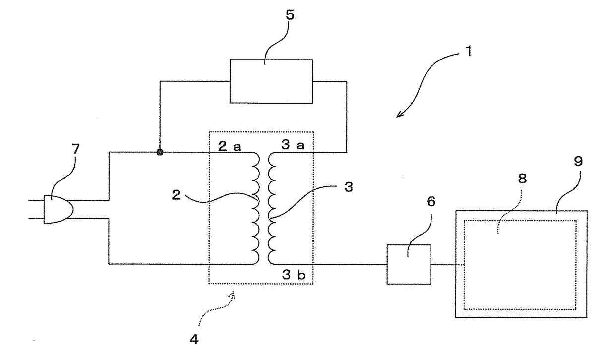
[0082]FIG. 1 is a circuit diagram showing a configuration of a space potential generator of the present invention.

[0083]As shown in the figure, a space potential generator 1 includes a transformer 4, which is formed by magnetically connecting a primary coil 2 and a secondary coil 3.

[0084]A terminal 3a, which is one terminal of the secondary coil 3, is connected to a terminal 2a, which is one terminal of the primary coil 2, via a feedback control circuit 5 for adjusting a voltage of the secondary coil 3. The other terminal (i.e. output terminal) 3b of the secondary coil 3 is connected to a static electricity discharger 8 via an output control portion 6 for applying a...


PUM


Abstract

A fryer includes a potential generator; and an oil tub installed with a discharging electrode of the potential generator. The potential generator includes a transformer that is composed of a primary coil and a secondary coil; a feedback control circuit that feeds back one terminal of the secondary coil to one terminal of the primary coil to adjust a voltage of the secondary coil; an output control portion that is provided on the other terminal of the secondary coil to impart a predetermined low frequency vibration to an output of the secondary coil which causes the discharging electrode physically vibrates;and the discharging electrode that is formed of a conductive material and provided on the other terminal of the secondary coil via the output control portion. A vibration frequency of the low frequency vibration applied is 40 Hz to 60 Hz which is determined by the output control portion.

Description

CROSS-REFERENCES TO RELATED APPLICATIONS[0001]This Application is a divisional application claiming the benefit of priority of the co-pending U.S. Utility Non-Provisional Patent Application No. 14 / 743,934 with a filing date of Jun. 18, 2015, which claims the benefit of priority of International Patent Application No. PCT / JP2014 / 080512, with an international filing date of Nov. 18, 2014, which designated the United States, and is related to the Japanese Patent Application No. 2014-027804, filed Feb. 17, 2014, the entire disclosures of all applications are expressly incorporated by reference in their entirety herein.BACKGROUND OF THE INVENTION[0002]1. Field of the Invention[0003]The present invention relates to a space potential generator that discharges a static electricity to a space to form an electric field, a freshness-keeping device to keep freshness of food or the like using the space potential generator, and a fryer provided with the space potential generator.[0004]2. Descript...

Claims


Application Information

Patent Timeline
Patent Type & Authority Applications(United States)
IPC IPC(8): A23L3/32F25D11/00F25D13/00A47J37/12
CPCA23L3/32A47J37/12F25D11/00F25D13/00H01T19/00H01T23/00A23V2002/00H01F27/29H01F27/42F25D23/12A23L3/26H01F38/14
Inventor GOTOKATO, TAKAYUKIKONDO, KANAKO
Owner GOTO KANETAKA
Why Eureka
Try Eureka