Multi-planar variable geometry zigzag cut articulating drilling system

Active Publication Date: 2017-09-14
THINK SURGICAL
View PDF0 Cites 19 Cited by
  • Summary
  • Abstract
  • Description
  • Claims
  • Application Information

AI Technical Summary

Benefits of technology

[0006]An articulating drill system is provided that includes a hand-held portion and a drill portion. At least two actuators are provided for controlling at least two axes of the drill portion. A navigation system is provided to control the actuators. In some embodiments, a tool is provided with the drill portion and adapted to inte

Problems solved by technology

Typically, oscillating saws are used to create an arcuate cut through the sternum, since it is difficult to properly close and reinforce a linear sternal cut for optimal cut planes consolidation, owing in part to the lack of a definitive reference or anchoring multiplanar structure to aid in sealing the closure.
Cutting an arcuate line, however, is practically difficult and inexact with existi

Method used


Image

  • Multi-planar variable geometry zigzag cut articulating drilling system
  • Multi-planar variable geometry zigzag cut articulating drilling system
  • Multi-planar variable geometry zigzag cut articulating drilling system

Examples


Example

Example 1

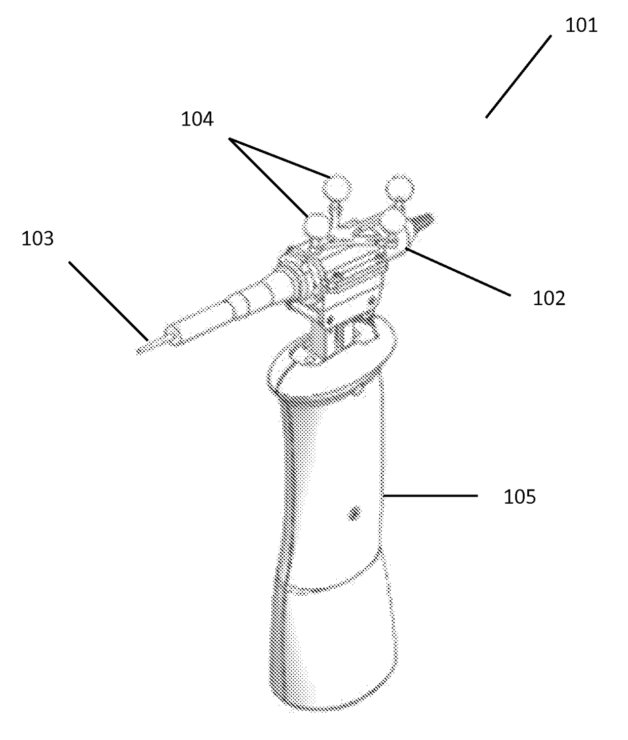
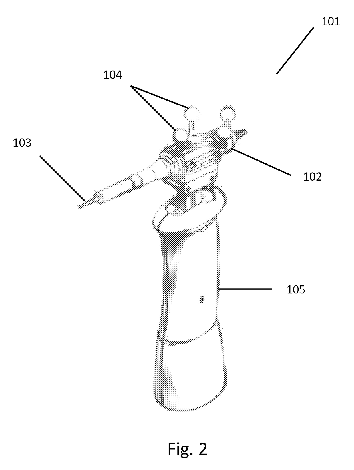
[0073]In cardiac surgery use the inventive system is used. The system includes an articulating hand-held drill tracked by a navigation system, where the device can articulate to keep the drill in a fixed plane of motion during a cut through a patient's sternum, independent of how the surgeon's hand moves, within limits, after the cutting is started. The surgeon uses trackable markers or reference devices mounted on the device itself, and on the bony anatomy on the sternum to compensate the cutting pattern for the movement of the sternum due to a patient's breathing in order to preserve a high accuracy and consistency cut.

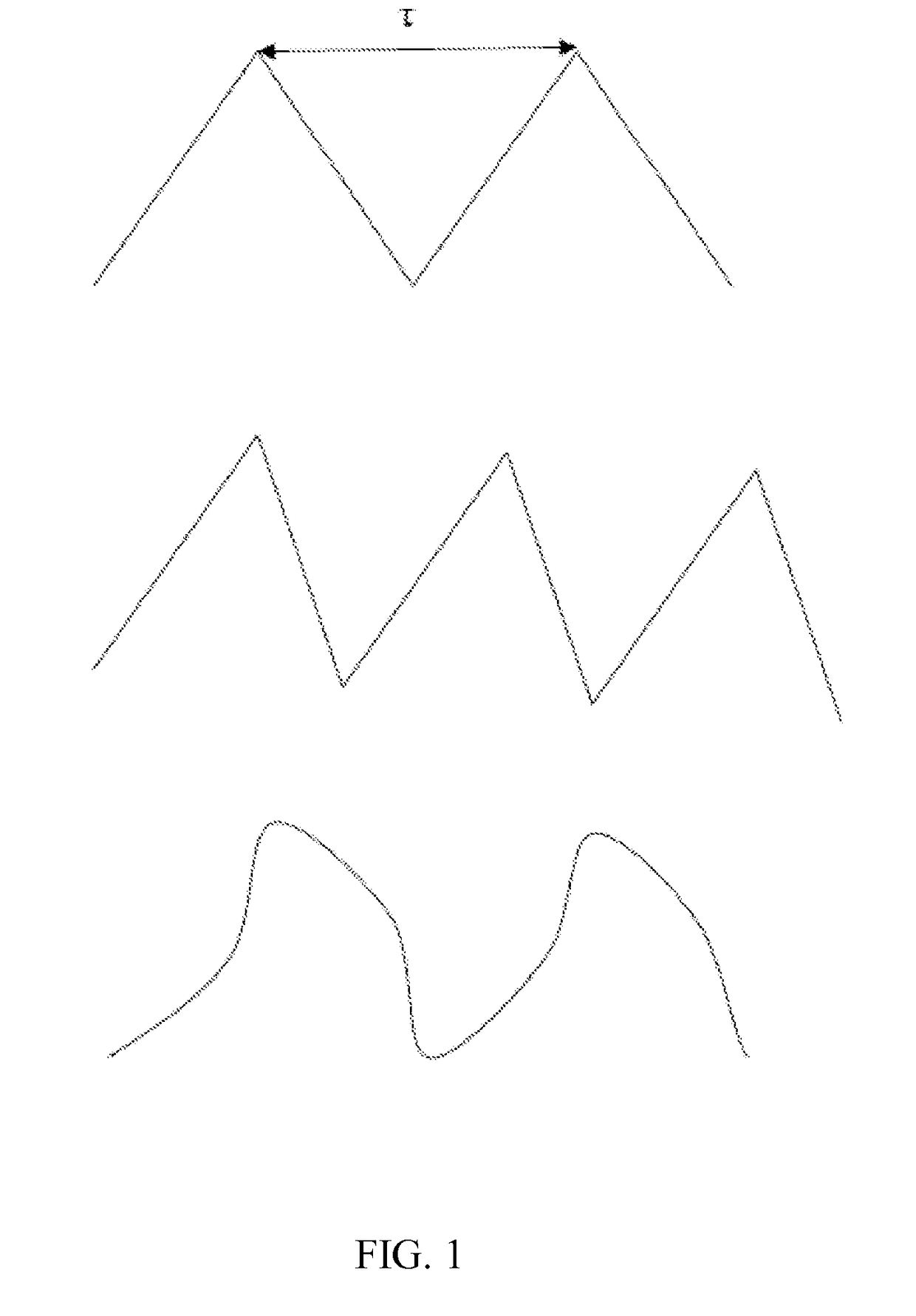
[0074]The surgeon begins cutting along the first plane of the cut. The surgeon reaches the desired area where the surgeon would like to alter the cut to a zigzag pattern and indicates to the device, by pulling a trigger that the plane of cutting should change.

[0075]A drill guard is used, located beyond the tip of the drill, riding along the underside of the...

Example

Example 2

[0076]The procedure of Example 1 is re-performed, however a pre-indicated endpoint is used and the pattern is pre-indicated by the surgeon before cutting by touching the tip of the device to a pattern drawn out by the surgeon on the patient's sternum. Upon completion the pre-indicated pattern is found to make closing the sternum after cardiac thoracic surgery has completed, much easier to perform and stable.

Other Embodiments

[0077]While at least one exemplary embodiment has been presented in the foregoing detailed description, it should be appreciated that a vast number of variations exist. It should also be appreciated that the exemplary embodiment or exemplary embodiments are only examples, and are not intended to limit the scope, applicability, or configuration of the described embodiments in any way. Rather, the foregoing detailed description will provide those skilled in the art with a convenient road map for implementing the exemplary embodiment or exemplary embodiment...


PUM


Abstract

An articulating drill system is provided that includes a hand-held portion and a drill portion. At least two actuators are provided for controlling at least two axes of the drill portion. A navigation system is provided to control the at least two actuators. In some embodiments, a tool is provided with the drill portion and adapted to interact with patient tissue. The drill portion can be modified to include at least two rigid objects in communication with the actuators and attached to the drill portion. The system can be used to make any linear cut within a deviation of 1.0 mm and 1.0?, or better in patient tissue.

Description

RELATED APPLICATIONS[0001]This application claims priority benefit of U.S. Provisional Application Ser. No. 62 / 054,009 filed 23 Sep. 2014; the contents of which are hereby incorporated by reference.TECHNICAL FIELD[0002]The present invention relates generally to computer-aided drill systems, and more specifically to a new and useful system for assisting with surgical procedures.BACKGROUND[0003]In thoracic surgery, the chest cavity often must be opened and the ribs retracted. Typically, oscillating saws are used to create an arcuate cut through the sternum, since it is difficult to properly close and reinforce a linear sternal cut for optimal cut planes consolidation, owing in part to the lack of a definitive reference or anchoring multiplanar structure to aid in sealing the closure. Cutting an arcuate line, however, is practically difficult and inexact with existing devices. Ideally, the sternum should be cut in a pattern where the two halves of the divided sternum can reunite in a m...

Claims


Application Information

Patent Timeline
IPC IPC(8): A61B34/20A61B90/00A61B17/16
CPCA61B34/20A61B17/1624A61B2034/2055A61B17/1626A61B2034/2065A61B90/36A61B17/16A61B17/1691A61B2017/00796A61B2090/309A61B2034/2048A61B2090/3945
Inventor SHALAYEV, STANZUHARS, JOELKANTROWITZ, ALLEN B.MUN, IN K.FULLER, DANGROVER, SIMON
Owner THINK SURGICAL
Why Eureka
Try Eureka