
Minimally invasive spine surgery drape

a spine surgery and drape technology, applied in the field of surgical drapes, can solve the problems of inability of surgeons to see the image intensifier or the tools on the floor, injury to patients, and more procedures, and achieve the effect of preventing or minimizing the entanglement of the devi

Inactive Publication Date: 2017-09-14
OSMAN SAID G
View PDF4 Cites 11 Cited by
  • Summary
  • Abstract
  • Description
  • Claims
  • Application Information

AI Technical Summary

Benefits of technology

The patent describes a surgical drape that allows surgeons and operating room staff to see through it while using an image intensifier to monitor the safety of tools and the patient. The drape has a main opaque portion that covers the body and transparent portions attached to the sides for added sterility. It also has designated pockets for irrigation fluid and operative tools, preventing entanglement. The drape can be connected at different points, such as sewing or using a hook and loop fastener. Overall, the technical effects include improved visibility and access for surgeons and a more organized surgical field.

Problems solved by technology

In this horizontal position, an opaque drape over the image intensifier makes it impossible for the surgeon to see the image intensifier or the tools on the floor.
Pulling the foot-operated tools away from underneath the drapes for the surgeon to visualize them often creates yet another problem, where the foot pedal may be too far from the patient to permit performance of the procedure, with the image intensifier in the horizontal position.
Often this leads to an awkward situation whereby an assistant has to place the surgeon's foot on the tool for him / her to perform surgery with the image intensifier in this horizontal position.
Turning the C-Arm from the vertical to the horizontal position may pull against these devices, or cause injury to the patient.
The multiplicity of cables and tubes can lead to entanglement and crowding of these structures on the surgical field, making the procedure more difficult.

Method used


Image

  • Minimally invasive spine surgery drape
  • Minimally invasive spine surgery drape
  • Minimally invasive spine surgery drape

Examples


Embodiment Construction

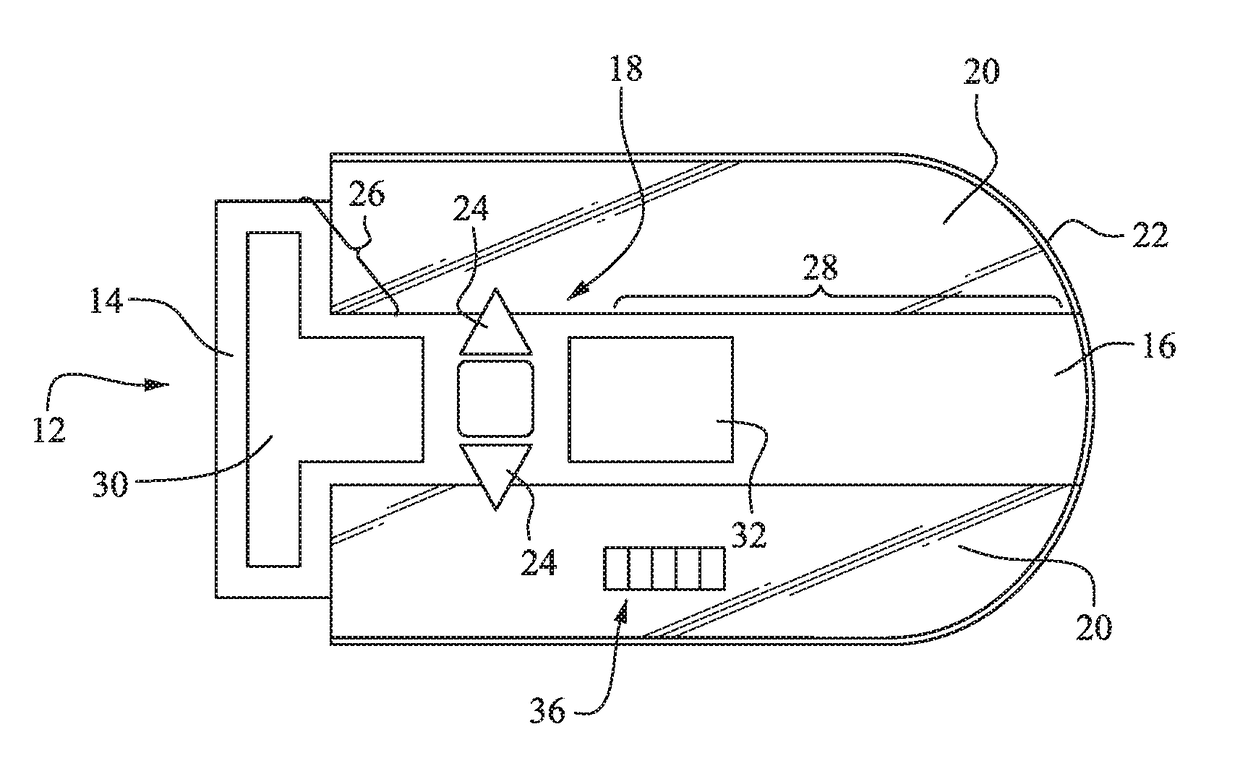
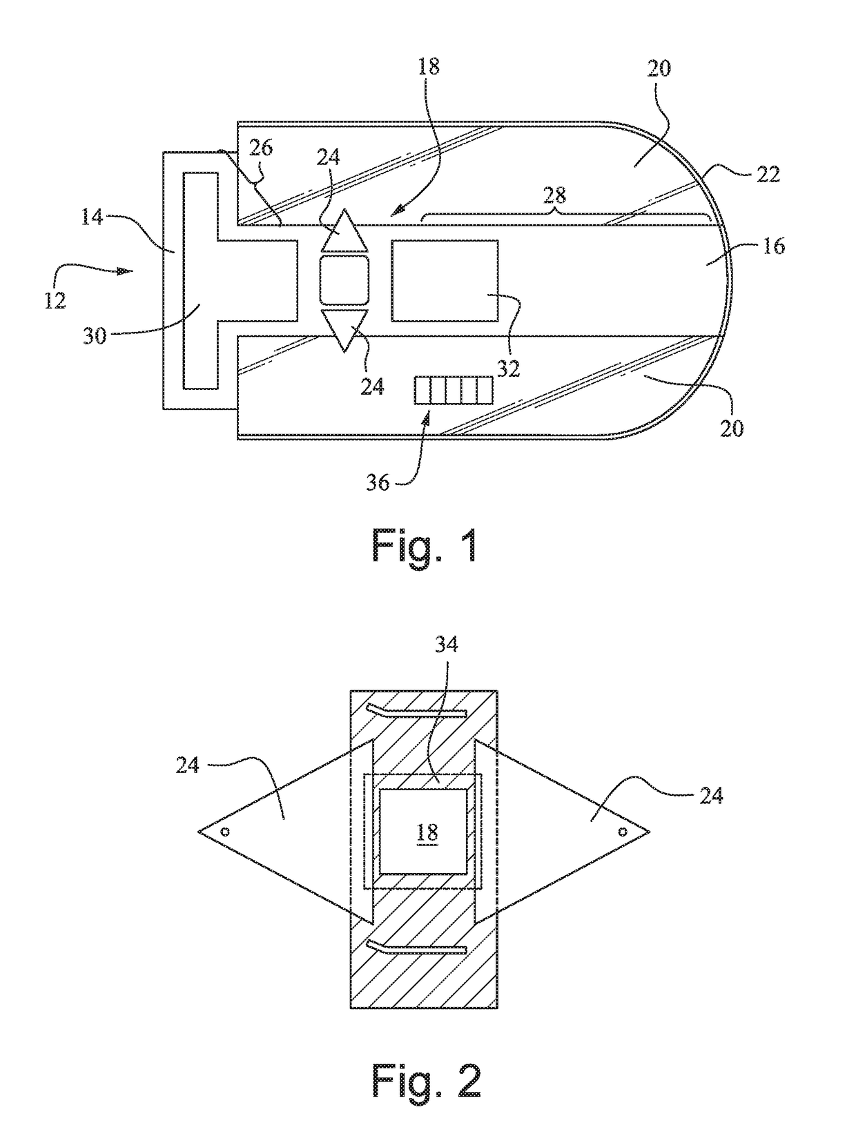
[0018]FIG. 1 is a plan view of the surgical drape according to a preferred embodiment. The drape includes a center section 12 extending longitudinally from a head end 14 to a foot end 16. This center section includes an operating window 18 and at least one surgical fluid collection pocket 24 disposed adjacent the operating window 18. Preferably, the center section 12 is formed of an opaque material.

[0019]A side section 20 is positioned on each longitudinal side of the center section 12 as shown. Preferably, the side sections are at least partially transparent. The center section 12 may be made out of a single sheet of material such as cloth or other appropriate fabric, or cut separately and attached together by known methods. The side sections 20 may be secured to the center section 12 with an adhesive, hook and loop fastener, or other known methods suitable for the described application.

[0020]An elastic band 22 extends through the outermost ends of the side sections 20 and across t...


PUM


Abstract

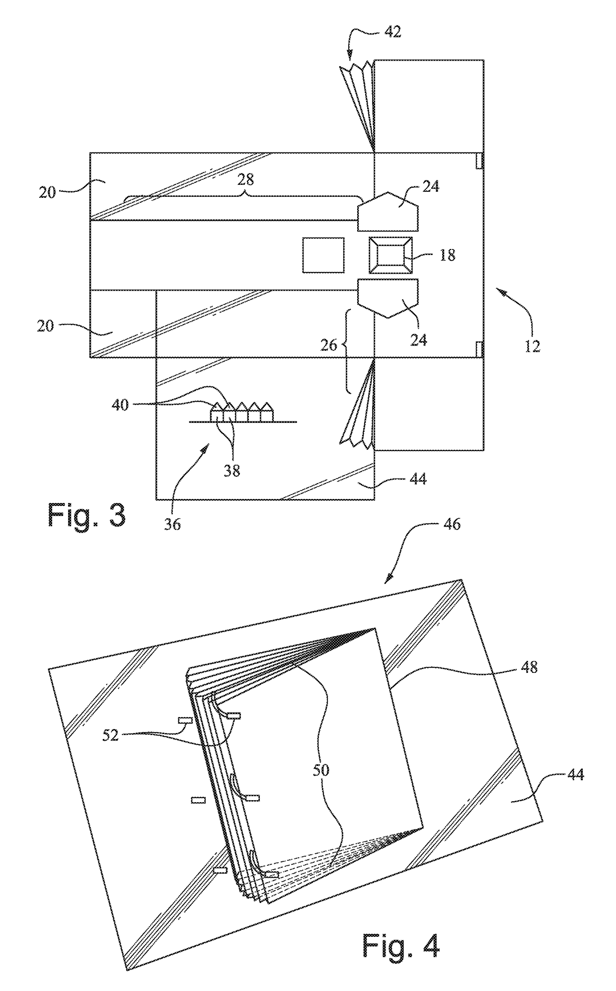
A surgical drape includes a center section having an operating window and extending longitudinally from a head end to a foot end, and a side section positioned on each longitudinal side of the center section. The side sections may be at least partially transparent. An elastic band extends through outermost ends of the side sections and across the foot end of the center section, and at least one surgical fluid collection pocket is disposed adjacent the operating window. Additional features of the drape may include a warming bladder and / or an extension section that is expandable to cover a machine adjacent the drape, such as an x-ray fluoroscope machine.

Description

CROSS-REFERENCES TO RELATED APPLICATIONS[0001](NOT APPLICABLE)STATEMENT REGARDING FEDERALLY SPONSORED RESEARCH OR DEVELOPMENT[0002](NOT APPLICABLE)BACKGROUND OF THE INVENTION[0003]The invention relates to surgical drapes and, more particularly, to a surgical drape including characteristics and functional components that promote a sterile surgical field, improve the surgeon's field of view, and increase patient comfort.[0004]Conventional surgical drapes are made of opaque fabrics, which may be made of cloth or synthetic materials. After sterile preparation of the operative site on the patient, the sterile drape is placed on the patient to cover the non-sterile part of the body, leaving only the surgical site exposed. Most of the surgical tools needed by the surgeon are placed either on a surgical tray, or in a sterile pocket, which may be part of the drape or come as its accessory. For open surgical procedures, there are only few tools that need to be on the floor, for example foot p...

Claims


Application Information

Patent Timeline
IPC IPC(8): A61B46/23A61B46/00A61F7/00
CPCA61B46/23A61F7/00A61B2046/234A61B2046/201A61B46/40A61F2007/0055A61B46/00A61B2017/00902
Inventor OSMAN, SAID G.
Owner OSMAN SAID G
Learn More