Centrifugal compressor

Inactive Publication Date: 2017-09-14
MITSUBISHI HEAVY IND LTD +1
View PDF2 Cites 10 Cited by
  • Summary
  • Abstract
  • Description
  • Claims
  • Application Information

AI Technical Summary

Benefits of technology

[0012]According to the centrifugal compressor of the present invention, in the vaneless diffuser, at least the first wall section of the hub casing protrudes toward the wall section side of the shroud casing facing the first wall section, the flow path width of the vaneless diffuser is smaller than the outlet width of the impeller, the hub casing includes an inclined wall section which has a portion between the outlet of the impeller and the inlet of the vaneless diffuser as a protruding end and connects the second wall section and the first wall section. Accordingly, the circulating flow blown o

Problems solved by technology

However, in the vaneless diffuser, if the flow angle increases, the loss increases, a rotating stall occurs in which flows are nonuniform in the ci

Method used


Image

  • Centrifugal compressor
  • Centrifugal compressor
  • Centrifugal compressor

Examples


example

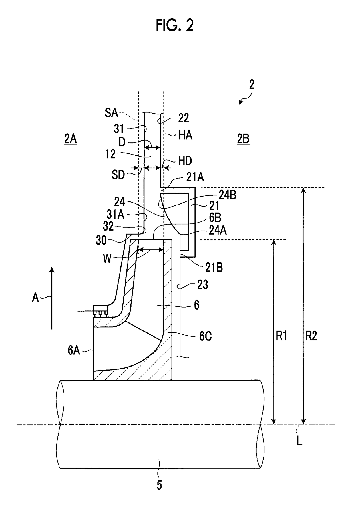
[0039]In Example, the wall section 31 of the shroud casing 2A further protrudes the shroud-side extension line SA, and the first wall section 22 of the hub casing 2B also further protrudes than the hub-side extension line HA. The shroud-side protrusion length SD is 17% of the width W of the discharge outlet 6B in the impeller 6, and the hub-side protrusion length HD is 23% of the width W of the discharge outlet 6B of the impeller 6. Accordingly, the ratio D / W between the flow path width D of the vaneless diffuser 12 and the width W of discharge outlet 6B is 0.6. In addition, a corner R portion having a small curvature radius R is provided between the wall section 31 of the shroud casing 2A and the horizontal wall 30 (steeply protrudes to SH side). In addition, in the inclined wall section 24 of the hub casing 2B, the trailing end 24B is provided in the vicinity of the inlet 21A of the fluid circulation flow path 21 and narrows the flow path width D of the vaneless diffuser 12 at a g...


PUM


Abstract

In order to reduce the rotating stall onset flowrate, this centrifugal compressor comprises: a vaneless diffuser (12) provided on a discharge outlet (6B) side of an impeller (6); and a fluid circulation flow path (21) having an inlet (21A) that opens into a first wall section (22) of a hub casing (2B) forming the vaneless diffuser (12) and also having an outlet (21B) that opens into a second wall section (23) of the hub casing (2B) facing a hub disk (6C) rear surface in the impeller (6). As a result of causing the first wall section (22) to protrude on to a wall section (31) side of the shroud casing (2A), the flow path width (D) of the vaneless diffuser (12) is smaller than the width (W) of the discharge outlet (6B) in the impeller (6). In addition, the hub casing (2B) comprises an inclined wall section (24) having a protruding end (24A) between the discharge outlet (6B) of the impeller (6) and the inlet of the vaneless diffuser (12), said inclined wall section (24) connecting the second wall section (23) and the first wall section (22).

Description

TECHNICAL FIELD[0001]The present invention relates to a centrifugal compressor in which a vaneless diffuser is provided on an outlet side of an impeller.BACKGROUND ART[0002]In general, an industrial centrifugal compressor is used in a petrochemical plant, a natural gas plant, or the like. In this kind of centrifugal compressor, a configuration is widely adopted, which uses a vaneless diffuser in which a vane is not provided in a diffuser portion on the outlet side of an impeller. The configuration which uses the vaneless diffuser has advantages in which the structure is simple, a loss decreases if a flow angle is appropriate, an operation range is wide, and a fluid vibrating force with respect to the impeller does not occur. However, in the vaneless diffuser, if the flow angle increases, the loss increases, a rotating stall occurs in which flows are nonuniform in the circumferential direction, and variation in pressures, shaft vibrations, vibrations of a discharge pipe, or the like ...

Claims


Application Information

Patent Timeline
IPC IPC(8): F04D29/44F04D29/42F04D29/28F04D17/10
CPCF04D29/441F04D29/284F04D29/4206F04D17/10F04D27/0207F04D29/681
Inventor MASUTANI, JOYOSHIDA, SATORU
Owner MITSUBISHI HEAVY IND LTD
Why Eureka
Try Eureka