Charging system

a charging system and charging state technology, applied in the direction of indicating/monitoring circuits, instruments, transportation and packaging, etc., can solve the problems of significant need for routine checking of the charged state of nickel metal hydride batteries, affecting the use frequency of devices, and reducing battery capacity, so as to prevent the imbalance of use frequency, accurately monitor the charging status, and eliminate the effect of erroneous operation

Inactive Publication Date: 2017-09-14
TAKASHIN
View PDF4 Cites 5 Cited by
  • Summary
  • Abstract
  • Description
  • Claims
  • Application Information

AI Technical Summary

Benefits of technology

[0011]According to the present invention, a charging system capable of simultaneously charging a plurality of the charge-scheduled devices, capable of eliminating the erroneous operation such as failing of the start of charging, capable of accurately monitoring the charged statuses of the plurality of the charge-scheduled devices, capable of preventing the imbalances in the use-frequencies of the devices ascribable to differences in the charging-period, and capable of individually managing the plurality of the charge-scheduled devices including the degradation of rechargeable batteries can be provided.

Problems solved by technology

In a situation that rechargeable batteries such as a lead-acid battery, a nickel cadmium (Ni—Cd) battery, a nickel metal hydride (Ni-MH) battery, and a lithium ion battery are used for medical devices, attention is necessary for not causing the over-discharge of the lead-acid battery, because the lead-acid battery has a characteristic such that an over-discharge of the lead-acid battery significantly degrades the performance of the lead-acid battery, and the degraded performance is not recovered.
The nickel metal hydride battery is weak against the over-discharge, and the complete discharge degrades performance of the nickel metal hydride battery so as to cause a decrease in the battery capacity.
In addition, since amount of the self-discharge of the nickel metal hydride battery is large, a routine checking of the charged state of the nickel metal hydride battery is significantly required.
The lithium ion battery has a risk of abnormal overheat at the times of the over-discharge and the over-charge.
However, in the invention disclosed in PTL 1, since the degree of charging-priority is determined based on the ratio of the battery remaining amount of each charge-scheduled device, a problem that a device having a possibility of being scheduled to be used at the earliest, after the charging the plurality of charge-scheduled devices, cannot be determined among the plurality of charge-scheduled devices with the priority exists.

Method used


Image

  • Charging system
  • Charging system
  • Charging system

Examples


first embodiment

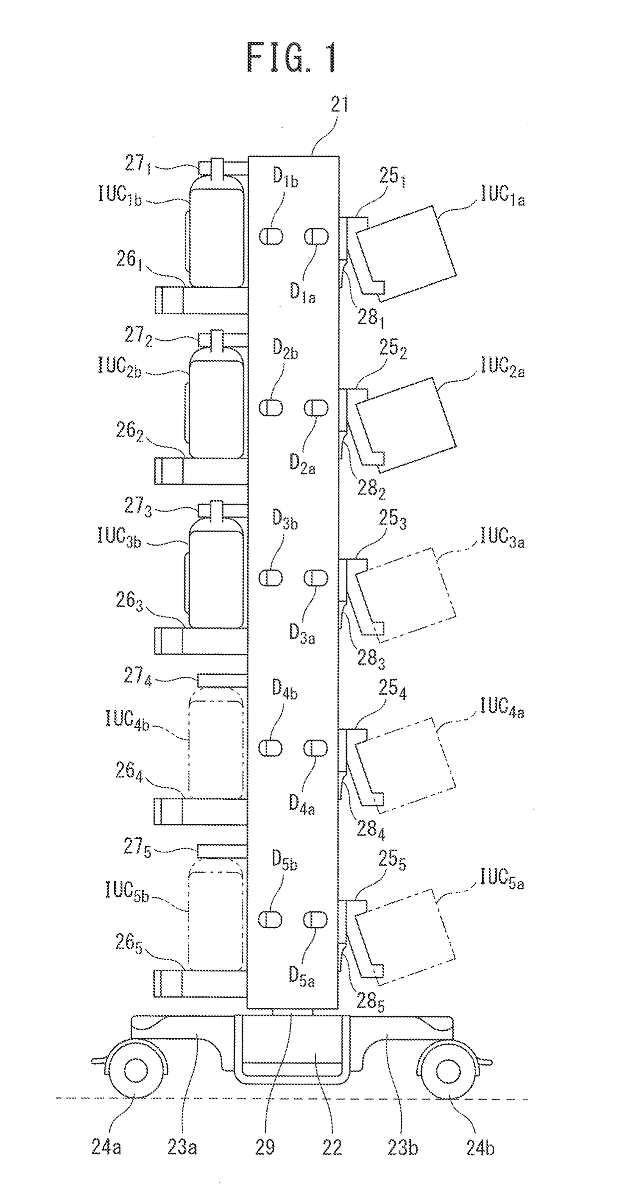
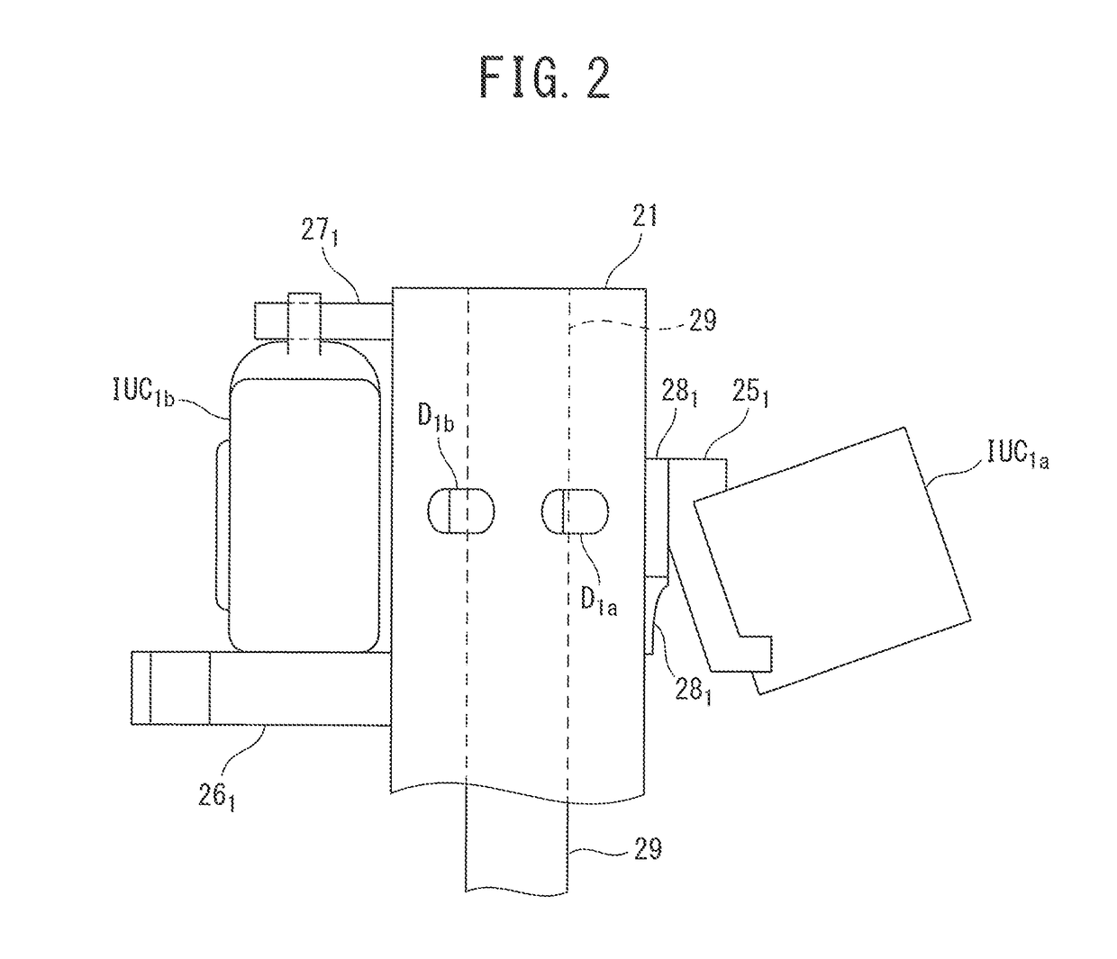
[0049]As illustrated in a side view of FIG. 1, in a charging system according to the first embodiment of the present invention, a plurality of charge scheduled devices IUC1a, IUC2a, . . . , IUC5a; IUC1b, IUC2b, . . . , IUC5b are arranged over side walls of a tower (21, 22, 23a, 23b, 23c, 23d, and 29), which extends in an elongated shape with a constant width. The tower (21, 22, 23a, 23b, 23c, 23d, and 29), a top view of which is illustrated in FIG. 3, includes a box-shaped display panel 21 extending in the height direction and a box-shaped pillar portion 29, which is connected to a center portion of one of the side faces of the display panel 21, such that a cross-sectional shape of the tower (21, 22, 23a, 23b, 23c, 23d, and 29) cut along a horizontal plane creates “T” shape. As illustrated in FIG. 3, because the top surface of the box-shaped display panel 21 extending in the height direction is recognized as a rectangular shape, the outer shape of the display panel 21 can be underst...

second embodiment

[0092]As illustrated by a front view in FIG. 17, a charging system according to a second embodiment of the present invention is built up from racks (71a, 71b, 72, 73, 211, 212, 213, and 214) instead of the tower (21, 22, 23a, 23b, 23c, 23d, and 29) described in the first embodiment. In other words, the racks (71a, 71b, 72, 73, 211, 212, 213, and 214) implementing a frame of the charging system according to the second embodiment includes a plurality of shelves 21i (=211, 212, 213, and 214), horizontal boards 71a and 71b that support the plurality of shelves 211, 212, 213, and 214, and a top board 73 that connects the upper end portions of the horizontal boards 71a and 71b. In addition, a power-breaker installation-case 72 that is a box of a vertically-long rectangular parallelepiped is arranged in the vertical direction along a rear end portion of the left horizontal board 71a. In FIG. 17, the power-breaker installation-case 72 located at the rear side is intermittently exposed at a ...

third embodiment

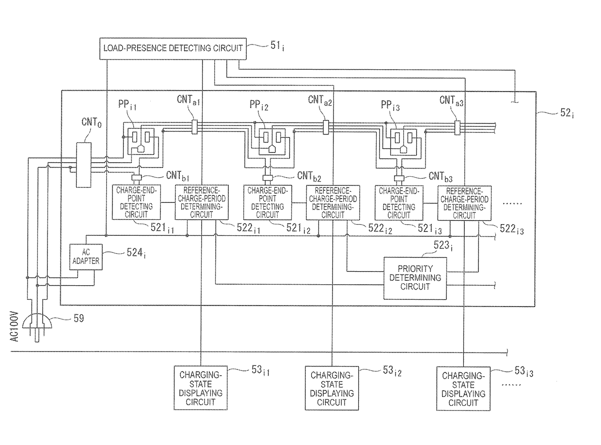
[0110]In the charging systems according to the first and second embodiments, when both the “load-presence detecting signal” and the “current-detecting signal” are fed, the predetermined period—for example, 15 hours—is counted, and, when a state in which the “current-detecting signal” is not fed is continued for a predetermined time—for example, ten minutes—, the counting of the predetermined period is skipped, and a “charging-completion signal” is transmitted to the priority-determining circuit. Then, based on the order in which the respective “charging-completion signals” are entered, the priority in the use order of a plurality of charge-scheduled devices are determined. However, in a charging system according to a third embodiment of the present invention, the charging-state of each charge-scheduled device can be individually determined, and the priority in the use order of charge-scheduled devices can be determined without counting the predetermined period and without causing a ...


PUM


Abstract

Power-feeding units to which charge-scheduled devices are connected, charge-end-point detecting-circuits detecting charging-start timing and charging-end timing, reference-charge-period determining-circuits measuring reference-charge-periods, a priority-determining circuit determining priority orders of uses of charge-scheduled devices based on the charging-periods of the charge-scheduled devices, and charging-state displaying circuits displaying under-charging or charge-completed and the priority in the use order of the charge-scheduled devices are included.

Description

TECHNICAL FIELD[0001]The present invention relates to a charging system and, particularly, to the charging system that simultaneously charges rechargeable batteries of multiple devices to-be-charged (charge-scheduled devices) and maintains the multiple charge-scheduled devices, as in the case of medical devices in a hospital or the like.BACKGROUND ART[0002]In a situation that rechargeable batteries such as a lead-acid battery, a nickel cadmium (Ni—Cd) battery, a nickel metal hydride (Ni-MH) battery, and a lithium ion battery are used for medical devices, attention is necessary for not causing the over-discharge of the lead-acid battery, because the lead-acid battery has a characteristic such that an over-discharge of the lead-acid battery significantly degrades the performance of the lead-acid battery, and the degraded performance is not recovered. The nickel cadmium battery has a large self-discharge behavior, and creates a large memory effect of battery, therefore, routine mainten...

Claims


Application Information

Patent Timeline
Patent Type & Authority Applications(United States)
IPC IPC(8): H02J7/00G01R31/36
CPCH02J7/0021G01R31/3606H02J7/0042H02J7/00H02J7/02H02J7/0044H02J7/0049G01R31/382
Inventor TANDAI, TOMOHISAYOSHIOKA, JUNMIKAMI, HIROAKIKOGAWA, JUNFUJITA, MASAKIAKAHIRA, TOSHIKI
Owner TAKASHIN
Why Eureka
Try Eureka