Power conversion device

a power conversion device and power conversion technology, applied in the direction of dynamo-electric converter control, dynamo-electric gear control, dynamo-electric brake control, etc., can solve the problems of unstable control of ac motors, broken main circuit components, etc., and achieve the effect of reliably suppressing the occurrence of overvoltage due to lc resonance phenomenon

Active Publication Date: 2017-09-14
MITSUBISHI ELECTRIC CORP
View PDF5 Cites 7 Cited by
  • Summary
  • Abstract
  • Description
  • Claims
  • Application Information

AI Technical Summary

Benefits of technology

[0014]In the power conversion device according to the present invention, as described above, an inverter is controlled by gate signals generated on the basis of signals obtained by respectively adding a d-axis voltage correction signal and a q-axis voltage correction signal to a d-axis voltage command value and a q-axis voltage command value. Thus, occurrence of overvoltage due to a LC resonance phenomenon can be reliably suppressed even in the case where, in addition to q-axis current, current is applied also on d axis by flux-weakening control.

Problems solved by technology

As a result, a main circuit component might be broken or control for the AC motor might become unstable.

Method used


Image

  • Power conversion device
  • Power conversion device
  • Power conversion device

Examples


embodiment 1

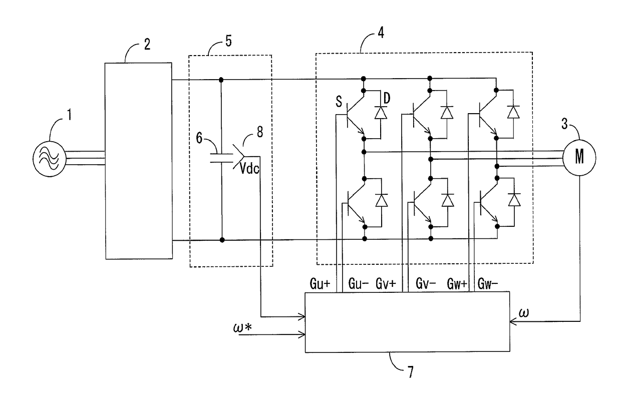
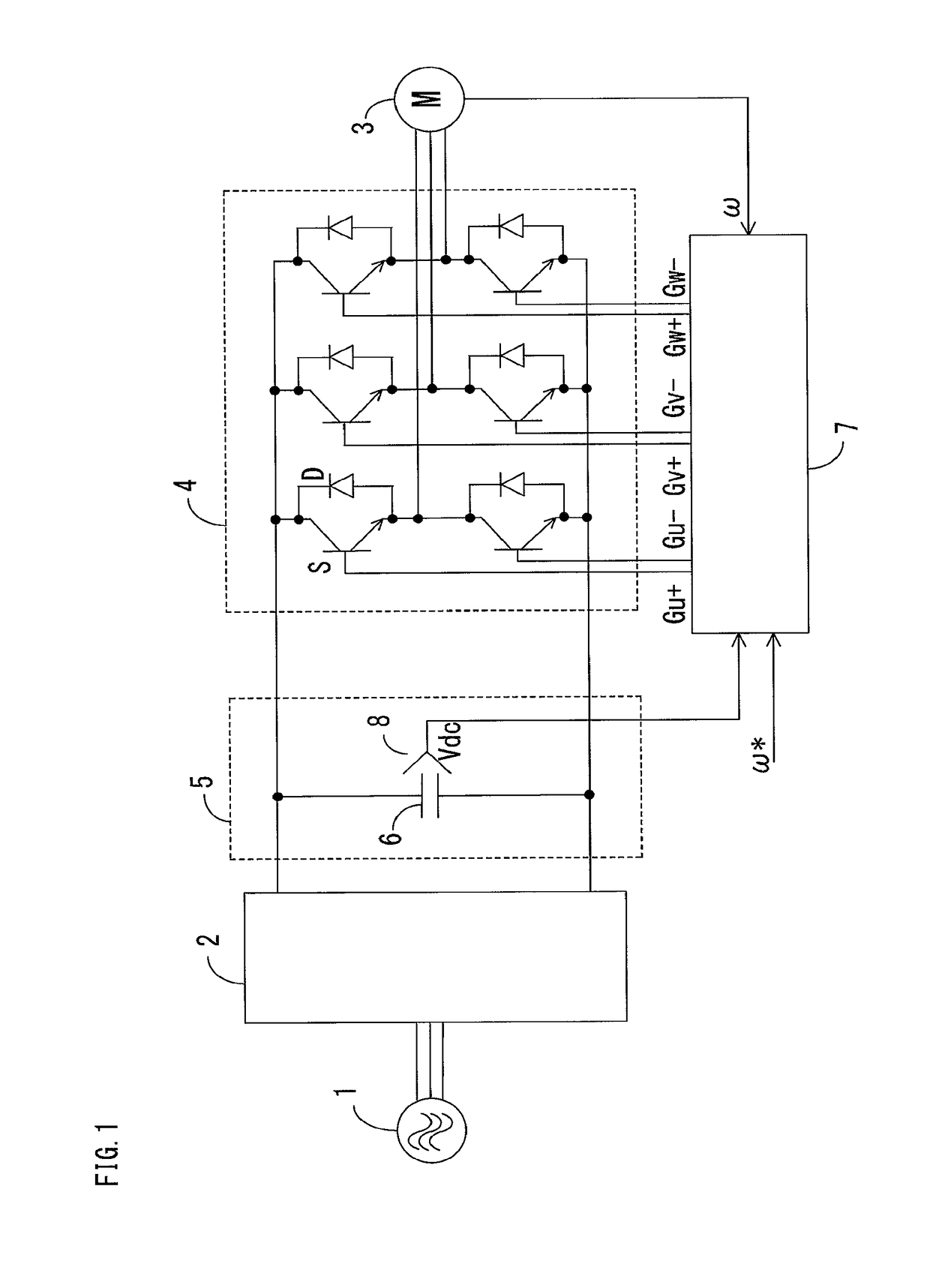
[0032]FIG. 1 is a diagram showing the entire configuration of a power conversion device according to embodiment 1 of the present invention. A main circuit of the power conversion device has a three-phase AC power supply 1, a DC link section 5 including a smoothing capacitor 6, a converter 2, and an inverter 4. The converter 2 converts three-phase AC voltage from the AC power supply 1, to DC voltage, and supplies the DC voltage to the DC link section 5. The inverter 4 converts the DC voltage of the DC link section 5 to AC voltage in a variable-voltage variable-frequency manner and supplies the AC voltage to an AC motor 3 which is an AC load.

[0033]Though the inside of the converter 2 is not shown, the converter 2 has, in general, a configuration in which diode elements are connected in a three-phase bridge form, and the inverter 4 has a configuration in which switching elements S and diode elements D connected in antiparallel thereto are connected in a three-phase bridge form.

[0034]Al...

embodiment 2

[0071]FIG. 5 is a diagram showing the internal configuration of a control unit 7 in a power conversion device according to embodiment 2 of the present invention. A difference from the case of FIG. 2 in embodiment 1 is that a resonance suppression control adjustment section 18 is provided in the resonance suppression control block 9. Hereinafter, the different part will be mainly described.

[0072]The condition in which the resonance suppression control is needed is that the resonance frequency of the LC resonance circuit coincides with a frequency six times as large as the power supply frequency, and that the output power of the inverter 4 is great.

[0073]FIG. 6 and FIG. 7 show examples of the relationship between consumed power in the AC motor 3 and oscillation of DC link voltage Vdc in the case where the resonance frequency coincides with a frequency six times as large as the power supply frequency. FIG. 6 shows the case where the consumed power is small, and FIG. 7 shows the case wh...

embodiment 3

[0090]FIG. 10 shows the internal configuration of a control unit 7 in a power conversion device according to embodiment 3 of the present invention. A difference from FIG. 2 in embodiment 1 is that the resonance suppression control block 9 performs control for correcting the d-axis current command value id* and the q-axis current command value iq* in addition to control for correcting the d-axis voltage command value vd* and the q-axis voltage command value vq*. Hereinafter, the different part will be mainly described.

[0091]There is a problem relevant to control response of the current control system having the d-axis current controller 10D and the q-axis current controller 10Q. From the perspective of the current control system, the voltage command corrected by the resonance suppression control is disturbance. If control response of the current control system is higher than the resonance frequency, operation is performed so as to cancel the voltage command corrected by the resonance...


PUM


Abstract

A power conversion device includes a high-pass filter for extracting an AC component of voltage Vdc of a DC link section, a multiplier for multiplying output VdcAC of the high-pass filter by a first gain K1 and outputting the result, a multiplier for multiplying output of the multiplier by a second gain K2 and outputting the result as a d-axis voltage correction signal vdcmp*, and a multiplier for multiplying output of the multiplier by a third gain K3 and outputting the result as a q-axis voltage correction signal vqcmp*. The gate signal generation section generates gate signals on the basis of a signal vd1 obtained by adding the d-axis voltage correction signal vdcmp* to a d-axis voltage command value vd* and a signal vq1 obtained by adding the q-axis voltage correction signal vqcmp* to a q-axis voltage command value vq*.

Description

TECHNICAL FIELD[0001]The present invention relates to a power conversion device which is configured by a converter and an inverter with a capacitor provided therebetween and drives an AC motor or the like, and in particular, relates to technique for suppressing occurrence of overvoltage due to an LC resonance phenomenon caused by an inductance component L that an AC power supply has and a capacitor C.BACKGROUND ART[0002]A main circuit of this type of power conversion device has a converter which converts AC voltage from an AC power supply to DC voltage and supplies the DC voltage to a DC link section including a smoothing capacitor, and an inverter which converts the DC voltage of the DC link section to AC voltage in a variable-voltage variable-frequency manner and supplies the AC voltage to an AC motor which is an AC load. When the power conversion device is connected to the AC power supply, an LC resonance circuit is formed by an inductance component L which the AC power supply ha...

Claims


Application Information

Patent Timeline
Patent Type & Authority Applications(United States)
IPC IPC(8): H02P21/22H02P21/14H02P6/15
CPCH02P21/22H02P21/14H02P6/15H02P21/05H02P21/06
Inventor ISHIKAWA, SHUTAKATO, MASANORIMARUMOTO, SHOTAROTAKEZAWA, RYUICHINISHIMURA, SHUNICHI
Owner MITSUBISHI ELECTRIC CORP
Why Eureka
Try Eureka