Guide assembly for forceps

a technology of forceps and guides, which is applied in the field of guide assemblies for instruments, can solve the problems of inability to correctly snap into place the prior art means for fastening, inability to accurately adjust the thickness of the coating on the inner side of the legs, etc., and achieves the effect of stable and simple manner

Active Publication Date: 2017-09-21
SUTTER MEDIZINTECHN
View PDF1 Cites 0 Cited by
  • Summary
  • Abstract
  • Description
  • Claims
  • Application Information

AI Technical Summary

Benefits of technology

[0009]Notwithstanding the above, layer thicknesses, which differ from part to part, can be created in response to the coating of the forceps legs. The hollow does not only create space for accumulations of the coating around the opening. Due to the fact that the hollow lends the collar certain elasticity, the guide elements can also still snap into place in the openings when the layer thickness varies. The elasticity resulting from the intentionally provided “weak point” in the area of the smallest material thickness on the collar thus also makes it possible to use the guide elements in the case of production tolerances of the coating of the forceps legs.
[0010]The hollow thus ensures the secure and accurate fit of the guide elements in the forceps legs.
[0012]In an embodiment of the invention, the fastening means extend substantially parallel to an axis of symmetry of the base body on the outer side of the base body and have a nose-like holding protrusion comprising at least one shoulder, which is located opposite the collar and which is positioned vertical to the axis of symmetry. The fastening means thus make it possible to snap the base body into place in the opening and thus provide for a simple assembly.
[0013]Advantageously, the fastening means are spaced apart from one another, and the fastening means are in particular formed by a plurality of snap-in pins, which are separated from one another by means of slits. The gaps provide for the elastic yielding of the fastening means. The guide elements can thus be easily inserted into the openings.
[0015]The conical shoulders of the protrusion and of the recess, which is complementary thereto, are designed in such a way that they can enter into a positive connection, so that during use of the forceps, divergence of the legs is prevented thereby maintaining the legs oriented relative to one another.
[0016]In an embodiment of the invention, the base body is embodied in one piece and forms a counter stop to the vertical shoulder of the nose-like holding protrusions. This embodiment can be produced in a particularly stable and simple manner.

Problems solved by technology

As a result, prior art means for fastening cannot snap into place correctly, for example, because the prior art means for fastening cannot engage undercuts in the openings above a certain layer thickness about the openings.
Each plug, however, can result in further inaccuracies with respect to the thickness of the coating on the inner sides of the legs in response to the coating.
However, the hollow arranged on the base body of each of the guide elements has the result that the edge of the opening remains free, even after the guide element is inserted and snapped into place in the opening on the inner side of a forceps leg.

Method used


Image

  • Guide assembly for forceps
  • Guide assembly for forceps
  • Guide assembly for forceps

Examples


Embodiment Construction

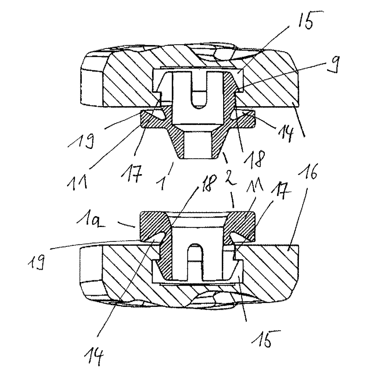
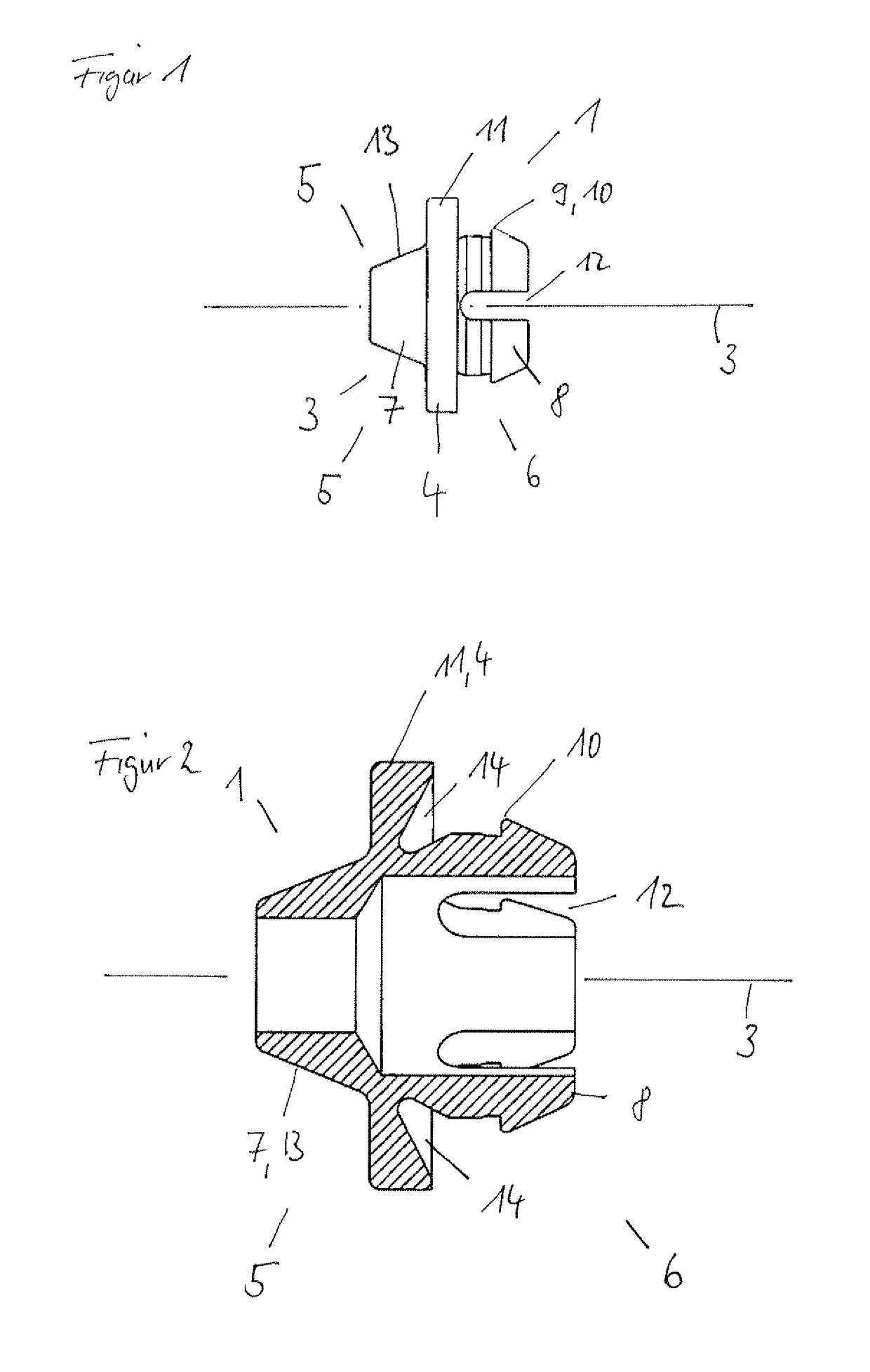
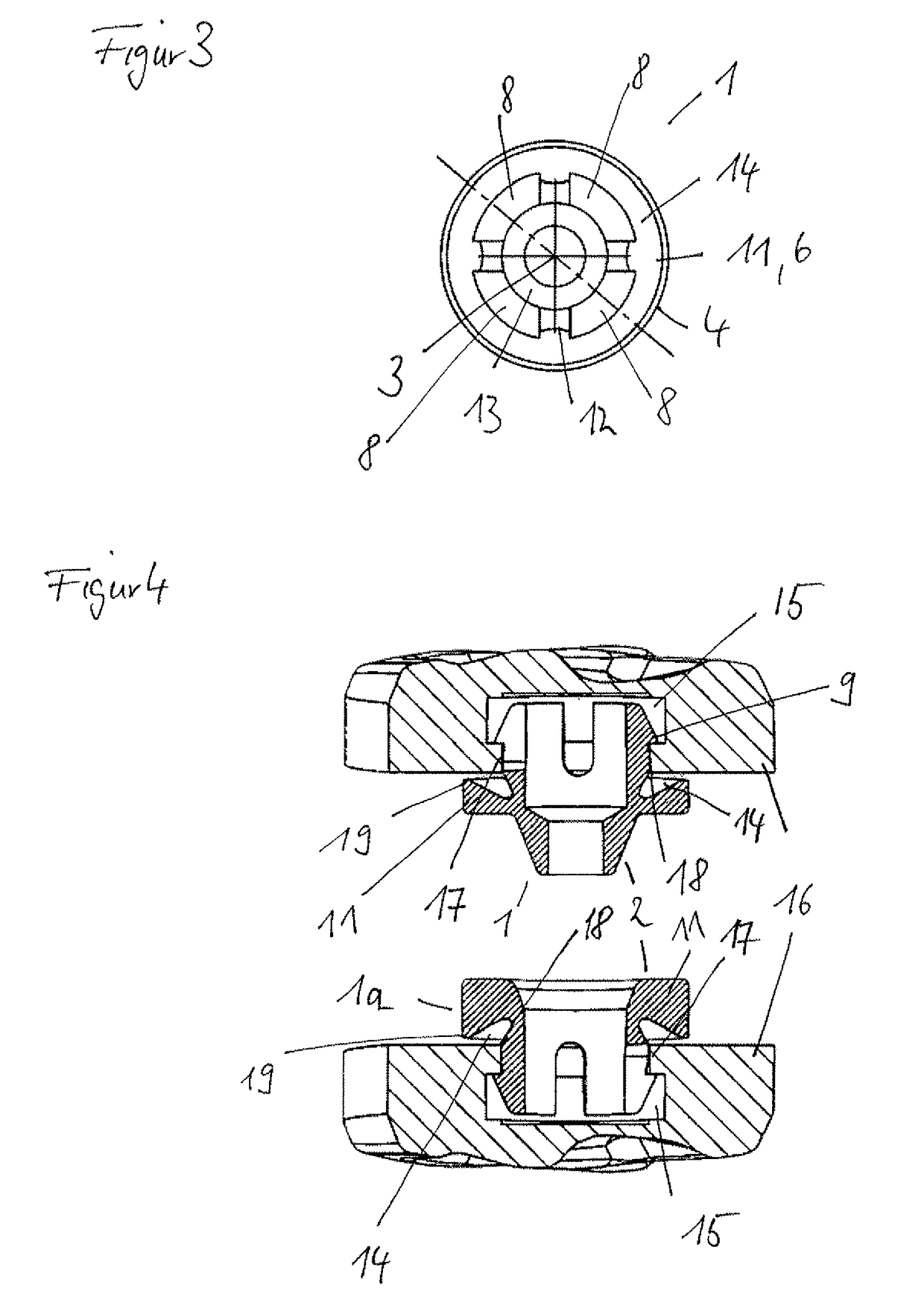
[0024]FIG. 1 shows a first guide element 1 of a guide assembly 2 including the first guide element 1 and a second guide element 1a in side view (see FIG. 4). The first guide element 1 consists of a base body 4, which is rotationally symmetrical to an axis of symmetry 3. The base body comprises an inner side 5 and an outer side 6.

[0025]A guide means 7, which is embodied as conically tapered appendage 13, is arranged on the inner side 5. The outer side 6 comprises means for fastening the guide assembly 2 to a blind hole 15 on the inner side of a forceps leg 16 (see FIG. 4). The fastening means are formed by snap-in pins 8, which extend on the outer side 6 of the base body 4, parallel to the axis of symmetry 3. The snap-in pins 8 have nose-like holding protrusion 9, which, based on the axis of symmetry 3, extend outwards at right angles. The holding protrusions 9 have a shoulder 10, which is positioned at right angles to the axis of symmetry 3 and which forms a counter stop to a collar...


PUM


Abstract

The invention relates to a guide assembly for an instrument comprising two legs, in particular forceps, the guide assembly comprising first and second guide elements, wherein the guide elements each comprise a base body, provision being made in each case on the outer side of the base body for an arrangement for snapping into place in an opening on an inner side of the legs of the instrument, provision being made on the inner side of the base body in the case of the first guide element for a protrusion and in the case of the second guide element for a recess, which is complementary to the protrusion, and provision being made in each case for a hollow on the outer side of the base body of the first as well as the second guide elements.

Description

FIELD OF THE INVENTION[0001]The invention relates to a guide assembly for an instrument comprising two legs, in particular forceps, wherein the guide assembly includes first and second guide elements.BACKGROUND[0002]Guides for forceps are known. They serve the purpose of absorbing shearing forces, which may occur, when compressing the forceps, and of preventing a divergence of the forceps legs. For the most part, the guides are embodied as appendages and / or recesses of the legs of the forceps and consist of the same material as the forceps legs. If they are electrosurgical forceps, however, the guides must consist of insulating material in order to prevent a short-circuit when compressing the legs. The guides then can not be embodied in one piece with the forceps legs any longer. The surfaces of electrosurgical instruments are provided with an insulating coating for the same reason. In the production process, the thickness of the coating is subject to fluctuations.[0003]Fluctuations...

Claims


Application Information

Patent Timeline
Patent Type & Authority Applications(United States)
IPC IPC(8): A61B18/14A61B90/00A61B17/28
CPCA61B18/1442A61B17/28A61B2090/034A61B2018/00083A61B90/08A61B2017/2825A61B90/11
Inventor HERMANN FAKLER, MICHAEL OTTO
Owner SUTTER MEDIZINTECHN
Why Eureka
Try Eureka