
Laminated Board and Application Thereof

a laminate board and laminate technology, applied in the field of laminate boards, can solve the problems of difficult to withstand a large weight, low strength, and the surface of the plastic panel tends to collapse, and achieves the effects of improving the strength, reducing the risk of slipping, and improving the scratch resistance and support strength

Pending Publication Date: 2022-09-15
JIANG JINGLEI
View PDF2 Cites 0 Cited by
  • Summary
  • Abstract
  • Description
  • Claims
  • Application Information

AI Technical Summary

Benefits of technology

The present invention provides a laminated board that is made of plastics and has the advantage of being lightweight while also being strong and impact-resistant. The laminated board has a predetermined number of bonding support structures that improve its strength. The outer layer is made of a material with high surface strength, scratch resistance, and oil stain resistance, while the inner layer is made of a material with low heat-plastic shrinkage ratio. When the intermediate layer is made of a material with high toughness, certain elasticity, and energy absorption, it provides a buffering effect to alleviate damage to the panel due to impact and drop, further improving its overall structural strength. The laminated board can be applied to different fields and achieve different requirements at the same time. The laminated board has better scratch resistance, impact resistance, and support strength while the manufacturing material of the laminated board itself does not require better scratch resistance, impact resistance, and support strength at the same time. The laminated panel includes a first panel member and a second panel member arranged opposingly and spacingly with the first panel member, and at least one portion of the second panel member extends to form at least one support portion, wherein the first panel member is supported on the support portion, thereby enhancing its structural strength. The first and second panel members form a hollow structure, thereby having a higher structural strength with lighter mass.

Problems solved by technology

However, for most plastic panels, there is a large drawback, that is relatively low in strength, making it difficult to withstand a large weight, and once bearing weight for too long, the surface of the plastic panel tends to collapse.
Conventional materials for manufacturing panels are typically wood or metal with sufficient support strength, but too heavy for transportation and installation.
Plastic-made panels, even though with lighter weight, are insufficient in strength.
Another problem is regarding the surface performance of the panel, wherein a surface of the panel made of wood or metal needs to be subjected to some special treatment to have better scratch resistance, waterproof, and oil-proof properties, but a plastic panel itself has better scratch resistance, water resistance, and oil resistance, relatively to wood and metal.
In fact, the defect of the lower strength of the plastic itself has not actually been overcome, and it does not fully exert the advantage of the light weight of the plastic panel as well.
The main part of the entire panel is still a wood or metal material, which is still relatively bulky.
In other words, the performance of conventional panels may meet one of the requirements, but it is difficult to achieve multiple requirements at the same time.

Method used


Image

  • Laminated Board and Application Thereof
  • Laminated Board and Application Thereof
  • Laminated Board and Application Thereof

Examples


embodiment 1

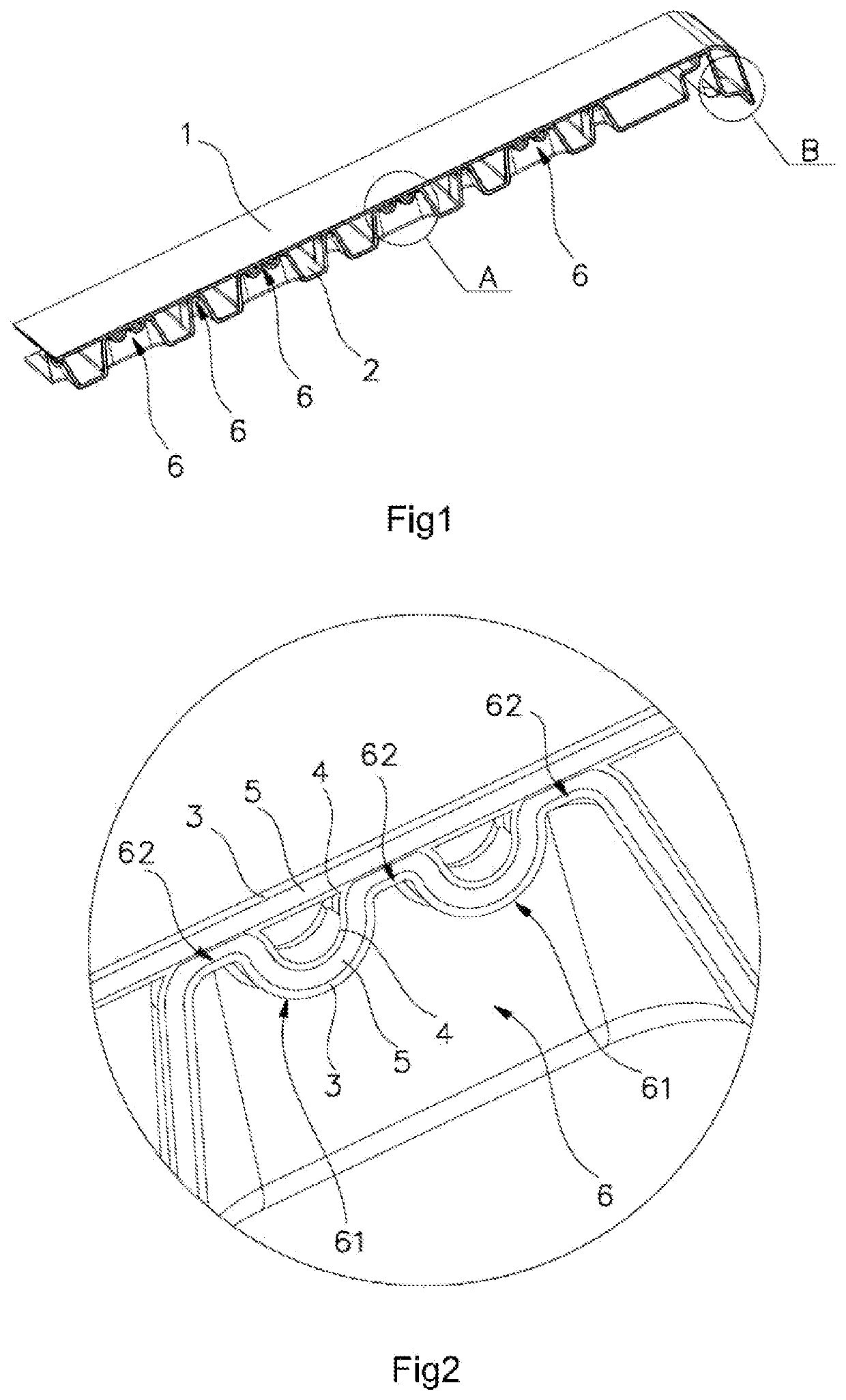
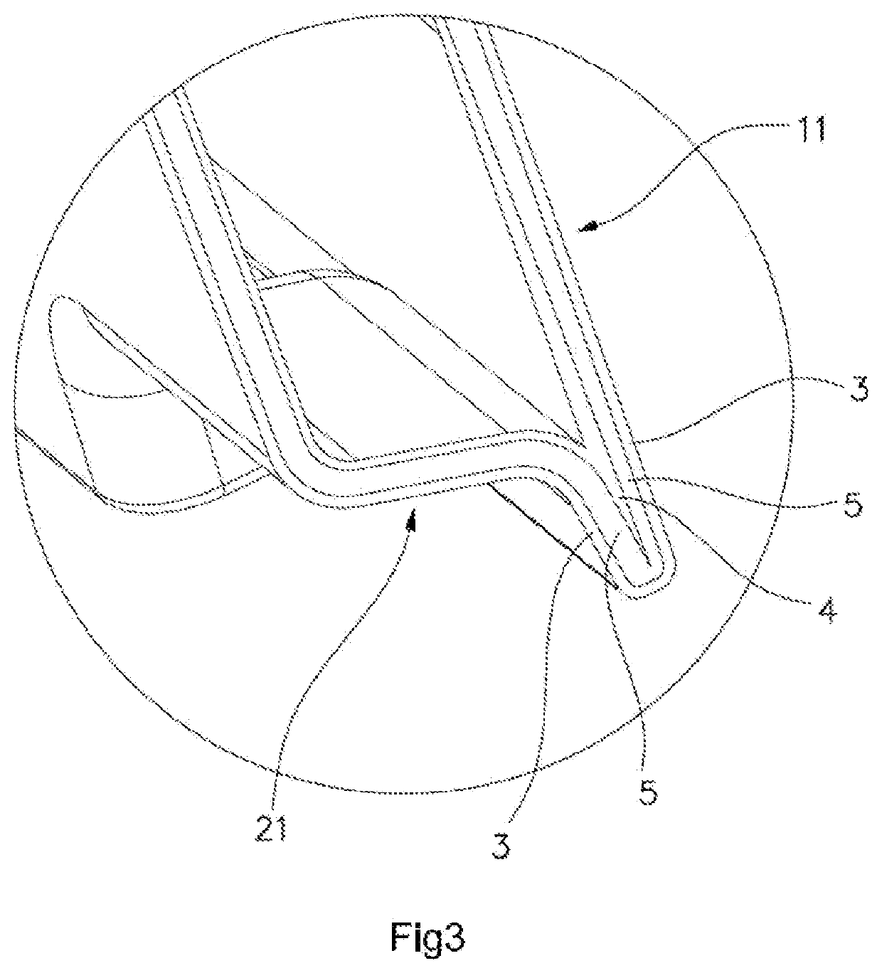
[0080]As shown in FIGS. 1-3, according to a first preferred embodiment of the present invention, the multi-layer laminated board according to the present embodiment comprises an upper panel member 1 and a lower panel member 2, wherein the upper panel member 1 and the lower panel member 2 form a hollow structure through a blow molding process.

[0081]Each of the upper panel member 1 and the lower panel member 2 of the present embodiment is a three-layer structure. That is each of the upper and lower panel members 1, 2 comprises an outer layer 3, an intermediate layer 5 and an inner layer 4, wherein the lower panel member 2 is recessed upwards, i.e., in the direction toward the upper panel member 1, until the inner layer 4 of the lower panel member and the inner layer 4 of the upper panel member 1 are fused and joined with each other to form a predetermined number of bonding support structures 6 distributed in a predetermined manner.

[0082]The edge structure of the blow-molded laminated ...

embodiment 2

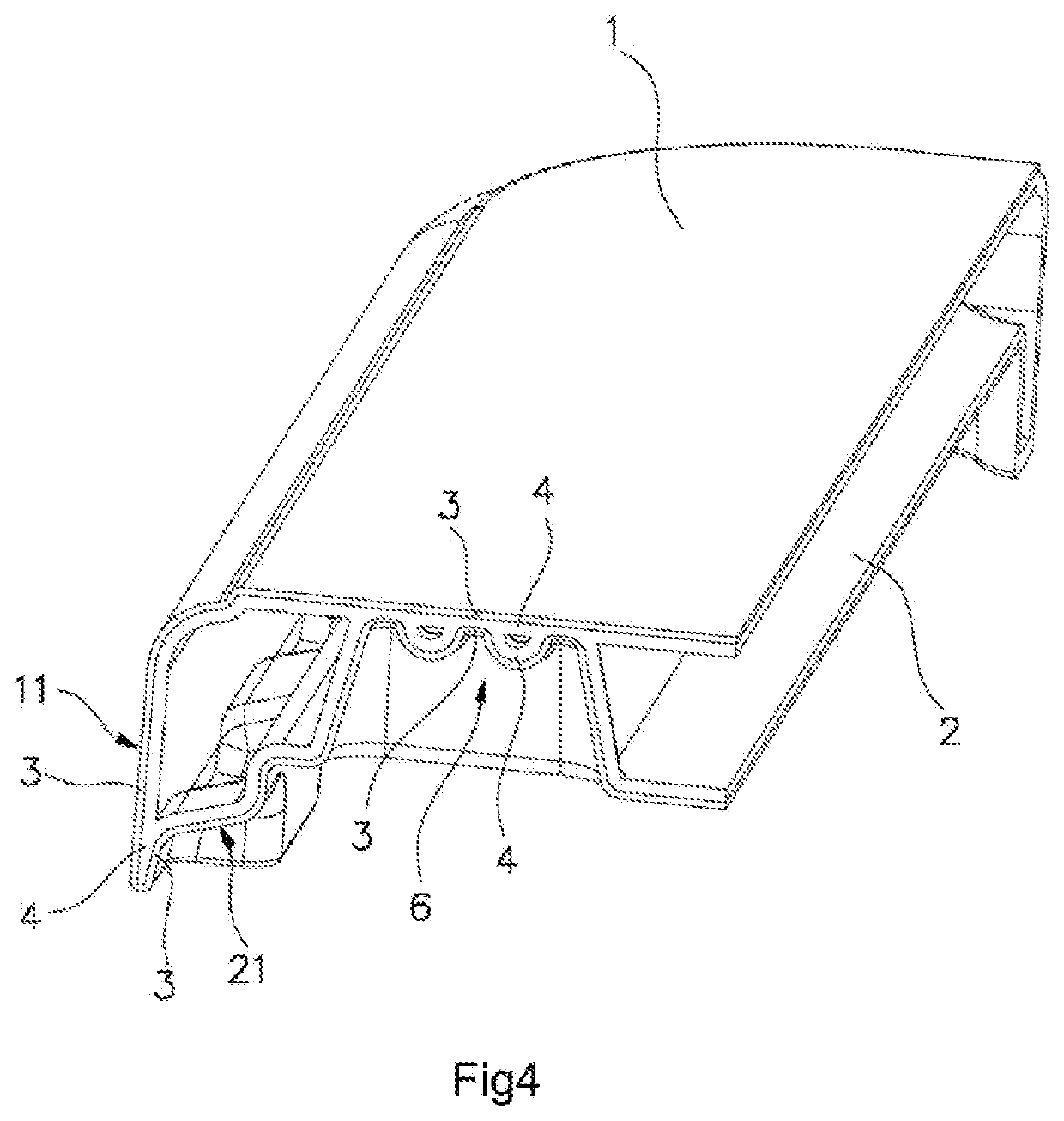
[0099]As shown in FIG. 4, according to a second preferred embodiment of the present invention, each of the upper panel member 1 and the lower layer 2 of the present embodiment is a double-layer structure, which comprises an outer layer 3 and an inner layer 4. Besides, the lower panel member 2 is recessed in the direction toward the upper panel member 1 till the inner layer of the lower panel member and the inner layer of the upper panel member 1 are fused and joined with each other so as to form a predetermined number of bonding support structures 6 distributed in a predetermined manner.

[0100]The material structure of the double-layer blow-molded laminated board is as follows: each of the outer layers 3 of the upper panel member 1 and the lower panel member 2 is made of high density polyethylene, and each of the inner layers 4 of the upper panel member 1 and the lower panel member 2 is made of a mixture of high density polyethylene, metallocene polyethylene, and calcium carbonate or...


PUM

PropertyMeasurementUnit
Structureaaaaaaaaaa
Strengthaaaaaaaaaa
Impact resistanceaaaaaaaaaa

Abstract

A laminated board and an application thereof. The laminated board comprises a first partial board, a second partial board, a first layer, and a second layer. The first layer is attached to the second layer, and a boundary is formed at the position where the first layer is connected to the second layer. The first partial board comprises one or two selected from the combination of at least part of the first layer and at least part of the layer. The second partial board comprises one or more selected from the combination of other at least part of the first layer and other at least part of the second layer. The first partial board and the second partial board are connected to each other at the edge and are spaced apart from each other to form a cavity. At least part of the second partial board extends to the first partial board to form at least one support structure. The first partial board can be supported in the support structure.

Description

BACKGROUND OF THE PRESENT INVENTIONField of Invention[0001]The present invention relates to the field of panel, and more particularly to a laminated board and application thereof.Description of Related Arts[0002]Plastic panels have been widely used in daily life, such as tables, chairs, walls, partitions, toys, and etc., all of which may be fabricated from plastic. A plastic panel has the advantages of light weight, rich color, and various shapes. However, for most plastic panels, there is a large drawback, that is relatively low in strength, making it difficult to withstand a large weight, and once bearing weight for too long, the surface of the plastic panel tends to collapse.[0003]Conventional materials for manufacturing panels are typically wood or metal with sufficient support strength, but too heavy for transportation and installation. Plastic-made panels, even though with lighter weight, are insufficient in strength. Another problem is regarding the surface performance of the...

Claims


Application Information

Patent Timeline
IPC IPC(8): B32B3/28B32B27/08B32B27/32B32B37/18
CPCB32B3/28B32B27/08B32B27/327B32B37/182B32B2250/03B32B2250/242B32B2323/043B29C49/0031B29C49/4812A47B13/08B32B27/20B32B2307/584
Inventor JIANG, JINGLEI
Owner JIANG JINGLEI
Learn More