System and method for transcatheter heart valve platform

a technology platform, which is applied in the field of system and method of transcatheter heart valve platform, can solve the problems of difficult implantation, relative danger, and still under developmen

Active Publication Date: 2017-09-21
ABBOTT CARDIOVASCULAR
View PDF1 Cites 17 Cited by
  • Summary
  • Abstract
  • Description
  • Claims
  • Application Information

AI Technical Summary

Benefits of technology

[0012]In some embodiments, the invention is a method for delivering a platform for reinforcing an annulus of a mitral valve in a heart of a patient, the heart including a right atrium, a left atrium, and a septum separating the right atrium from the left atrium. The method comprises passing, via a femoral artery of a patient, a catheter having a sheath covering a tube formed from a metal into the right atrium then through the septum into the left atrium, the tube being cut to define a structure that includes an annular portion defining a bore and an axis that extends along the bore, and further defining at least one opening in a circumferential surface of the annular portion, a plurality of upper elements attached to an upper perimeter of the annular portion and extending axially, and a plurality of lower elements attached to a lower perimeter of the annular portion and extending axially. Once the catheter has been so inserted, the tube is inserted into the annulus of the mitral valve. Then the sheath is withdrawn from covering the lower elements, but leaving the sheath covering the annular portion and the plurality of upper elements. Then, the plurality of lower elements are bent by imparting a plastic deformation to the metal until the plurality of lower elements extend radially so as to be positioned beneath the mitral valve. Thereafter, the sheath is withdrawn from covering the annular portion and the plurality of upper elements, whereafter, the plurality of upper elements are bent by imparting a plastic deformation to the metal until each of the plurality of upper elements extends radially so as to be positioned above the mitral valve.
[0013]In some embodiments, the annular portion occupies a first cylindrical profile having a first diameter, and the plurality of lower elements prior to being bent occupy a second cylindrical profile having a second diameter smaller than the first diameter, and wherein bending the plurality of lower elements includes moving a piston distally through the annular portion and engaging each of the plurality of lower elements with the piston, the piston having a third diameter greater than the second diameter. In embodiments, moving a piston distally through the annular portion and engaging each of the plurality of lower elements with the piston is simultaneously accompanied by restraining the first diameter of the annular portion against expansion. In embodiments, restraining the annular portion against expansion of the first diameter includes positioning a resilient ring around the lower perimeter of the annular portion, and in some embodiments, positioning a resilient ring includes positioning a distal end of the sheath around the lower perimeter of the annular portion.
[0014]In some embodiments, the method of the invention includes expanding the first diameter of the annular portion by imparting a plastic deformation to the metal. In this case, in further embodiments, expanding the first diameter of the annular portion includes expanding the first diameter until the annular portion is in contact with the annulus of the mitral valve along a continuous circumference of the annular portion. In some embodiments, expanding the first diameter of the annular portion includes expanding the third diameter of the piston. In yet further embodiments, bending the plurality of upper elements includes applying an axially oriented force on each of the plurality of upper elements. Some embodiments may include the further step of applying a force having a radially outward component to each of the plurality of upper elements. In some embodiments, applying a force having a radially outward component to each of the plurality of upper elements includes applying a moving force to a proximal extremity of each of the plurality of upper elements. In other embodiments, applying an axially oriented force includes applying a force to a proximal extremity of each of the plurality of upper elements. In yet other embodiments, applying an axially oriented force includes restraining the annular portion against distal movement, and in some embodiments, restraining the annular portion against distal movement includes inserting a pin into the at least one opening. These embodiments provide a novel and useful method for delivering a platform for reinforcing an annulus of a mitral valve in a heart of a patient.
[0015]In another embodiment, the invention is a system for delivering a platform to support a prosthetic mitral valve in a patient's heart. The system comprises a delivery catheter that includes a slidable sheath, a tube positioned within the slidable sheath and being cut to define a structure that includes: an annular portion defining a bore and an axis that extends along the bore, and further defining at least one opening in a circumferential surface of the annular portion; a plurality of upper elements attached to an upper perimeter of the annular portion and extending axially; and a plurality of lower elements attached to a lower perimeter of the annular portion and extending axially. A piston configured to slide within the tube is provided, the piston defining a lumen that receives at least one pin configured to slide out of the lumen so as to pass through the at least one opening. In some embodiments, the at least one pin is two pins, and the two pins are separated from each other by a spring configured to urge the two pins apart from each other. In some embodiments, each of the two pins is attached to a retraction wire that extends inside the lumen, the retraction wire being attached to each of the two pins, whereby the two pins are urged towards each other when the retraction wire is pulled proximally. In some embodiments, the slidable sheath includes a resilient ring at a distal end of the slidable sheath. In further embodiments, the resilient ring is made of metal. In yet other embodiments, the annular portion occupies a first cylindrical profile having a first diameter, and the plurality of lower elements occupy a second cylindrical profile having a second diameter smaller than the first diameter. In some embodiments, the piston has an outer circumferential surface having a third diameter that is smaller than the first diameter but larger than the second diameter, whereby distal movement of the piston applies a force against the plurality of lower elements thus to urge each of the plurality of lower elements to bend away from the axis. In some embodiments, the piston includes a means for causing the outer circumferential surface to expand. In other embodiments, the system includes a means for applying a distal force against a proximal end of each of the plurality of upper elements and thus to urge the plurality of upper elements to bend away from the axis. The embodiments thus described provide a novel and useful system for delivering a platform to support a prosthetic mitral valve in a patient's heart.

Problems solved by technology

Their design is stent based but requires placement through the apex of the left ventricle (LV), which can be relatively dangerous particularly in patients with CHF and IMR.
However, many of these systems are still under development, and are difficult to implant.

Method used


Image

  • System and method for transcatheter heart valve platform
  • System and method for transcatheter heart valve platform
  • System and method for transcatheter heart valve platform

Examples


Embodiment Construction

[0030]In some embodiments, as described with reference to the figures, the invention comprises a system and method for installing a platform or an annulus to reinforce the natural annulus of a diseased mitral valve in a patient.

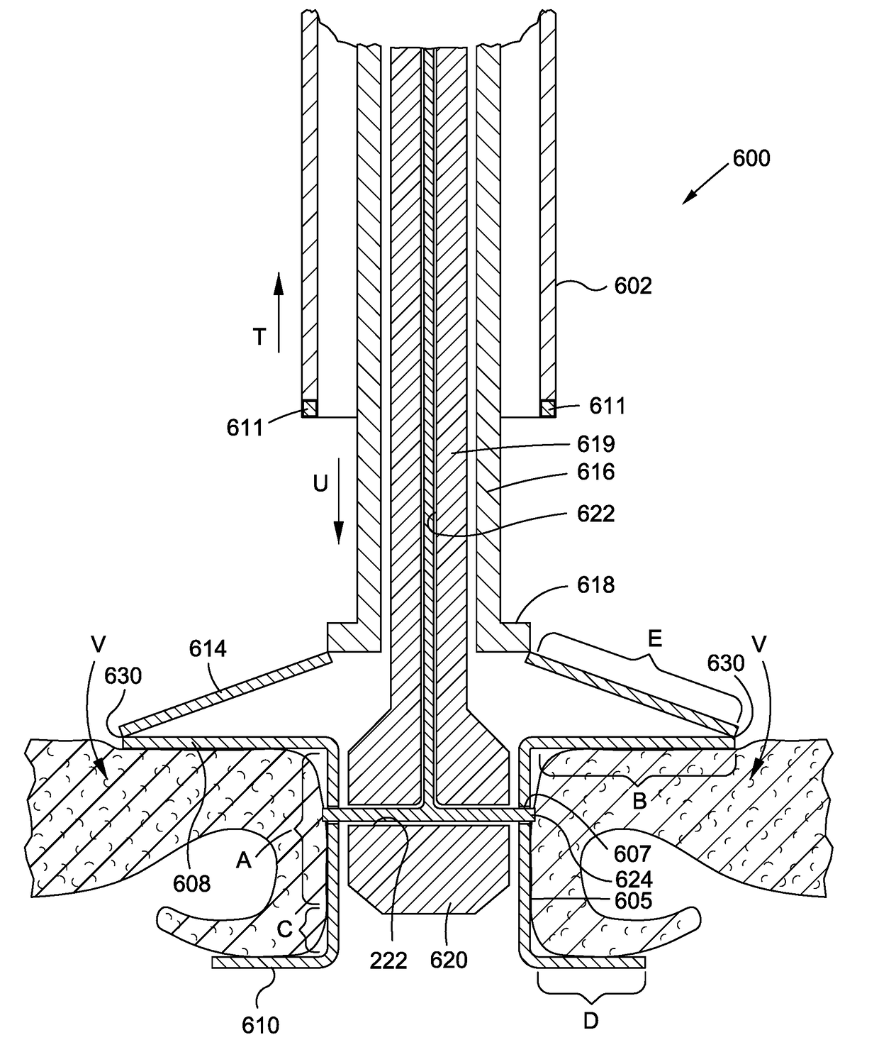
[0031]Turning now to an embodiment of the invention, and referring to FIG. 4, a distal end of a delivery catheter 600 is shown, extending downwardly and inserted between the leaflets 402 of a mitral valve in a patient's heart using known technique. The external sheath of the catheter may be of a kind that is known in the art, for delivering an implant into the left ventricle of the heart of a patient.

[0032]At its distal end, the catheter is surrounded by a sheath 602 that is slidably retractable in relation to other internal elements of the catheter. (Stated differently, other internal elements of the catheter are distally slidable in relation to the sheath.) Held within the sheath is a stent-like tube 606 in a compressed condition, which, at this stage befor...


PUM


Abstract

A method for delivering a platform for reinforcing an annulus of a mitral valve: Passing a catheter having a sheath covering a tube formed from a metal into the left atrium, the tube including: an annular portion defining at least one opening, a plurality of upper elements attached to an upper perimeter of the annular portion and extending axially, and a plurality of lower elements attached to a lower perimeter of the annular portion. Inserting the tube into the annulus of the mitral valve; withdrawing the sheath, but leaving the sheath covering the annular portion and the upper elements; bending the lower elements until the lower elements extend radially so as to be positioned beneath the mitral valve; then withdrawing the sheath from covering the annular portion and the upper elements; bending the upper elements until the upper elements extend radially so as to be positioned above the mitral valve.

Description

BACKGROUND[0001]The present invention relates to mitral valve prosthetic devices and, more particularly, to platforms into which mitral valve prosthetic devices may be deployed via a transcatheter approach.[0002]The use of a catheter-based percutaneous valved stent has been shown to be feasible in replacing in humans both the pulmonic and the aortic valves. The pulmonic valve was the first to be successfully replaced by a percutaneous approach and is the furthest along in development. There are currently two aortic valve products in clinical trials and more in development that are deployed percutaneously.[0003]In addition to the percutaneous catheter-based aortic valve replacement devices there are three other types of replacement valve prosthesis known to the applicants that use different technologies. One known technology, named the Transcatheter Mitral Valve Implantation (TMVI), is being developed by CardiAQ Valve Technologies (CVT). This design is fundamentally a shape memory st...

Claims


Application Information

Patent Timeline
Patent Type & Authority Applications(United States)
IPC IPC(8): A61F2/24
CPCA61F2/243A61F2/2436A61F2/2409A61F2/2418A61F2250/0071
Inventor KRONE, RYAN T.
Owner ABBOTT CARDIOVASCULAR
Why Eureka
Try Eureka