Device for treating mitral valve regurgitation

a technology for mitral valves and devices, applied in the field of devices for treating mitral valve regurgitation, can solve the problems of distorting the shape of the mitral valve, reducing the ejection volume of the eft ventricle, and the left ventricle to compensate with a larger stroke volume, so as to reduce fatigue, reduce lateral distance, and dampen the shock to the supporting tissues

Inactive Publication Date: 2007-03-22
MEDTRONIC VASCULAR INC
View PDF54 Cites 360 Cited by
  • Summary
  • Abstract
  • Description
  • Claims
  • Application Information

AI Technical Summary

Benefits of technology

[0021] Another aspect of the present invention is a method of treating mitral valve regurgitation by affecting a mitral valve annulus. A first wall of a chamber of a heart is pierced. A distal anchor is engaged with a second wall of the heart chamber. A proximal anchor is engaged with the first wall of the heart chamber. A tension member links the proximal and distal anchors applies a constant tension force to reduce the lateral distance between the two anchors.
[0022] Devices disclosed herein are advantageous over previously disclosed devices in that they dampen shock...

Problems solved by technology

This results in reduced ejection volume from the eft ventricle, causing the left ventricle to compensate with a larger stroke volume.
The increased workload eventually results in dilation and hypertrophy of the left ventricle, further enlarging and distorting the shape of the mitral valve.
If left untreated, the condition may result in cardiac insufficiency, ventricular failure, and death.
This is a complex, invasive surgical procedure with the potential for many complications and a long recovery period.
Rigid annuloplasty rings have the disadvantage of causing the mitral valve annulus to be rigid and unable to flex in response to the contractions of the ventricle, thus inhibiting the normal movement of the mitral valve that is required for it to function optimally.
This eventually leads to scar tissue formation and loss of flexibility and function of the mitral valve.
Similarly, combination rings must generally be sutured in place and also cause scar tissue formation and loss of mitral valve flexibility and function.
However, the coronary sinus in a particular individual may not wrap around the heart fa...

Method used


Image

  • Device for treating mitral valve regurgitation
  • Device for treating mitral valve regurgitation
  • Device for treating mitral valve regurgitation

Examples


Embodiment Construction

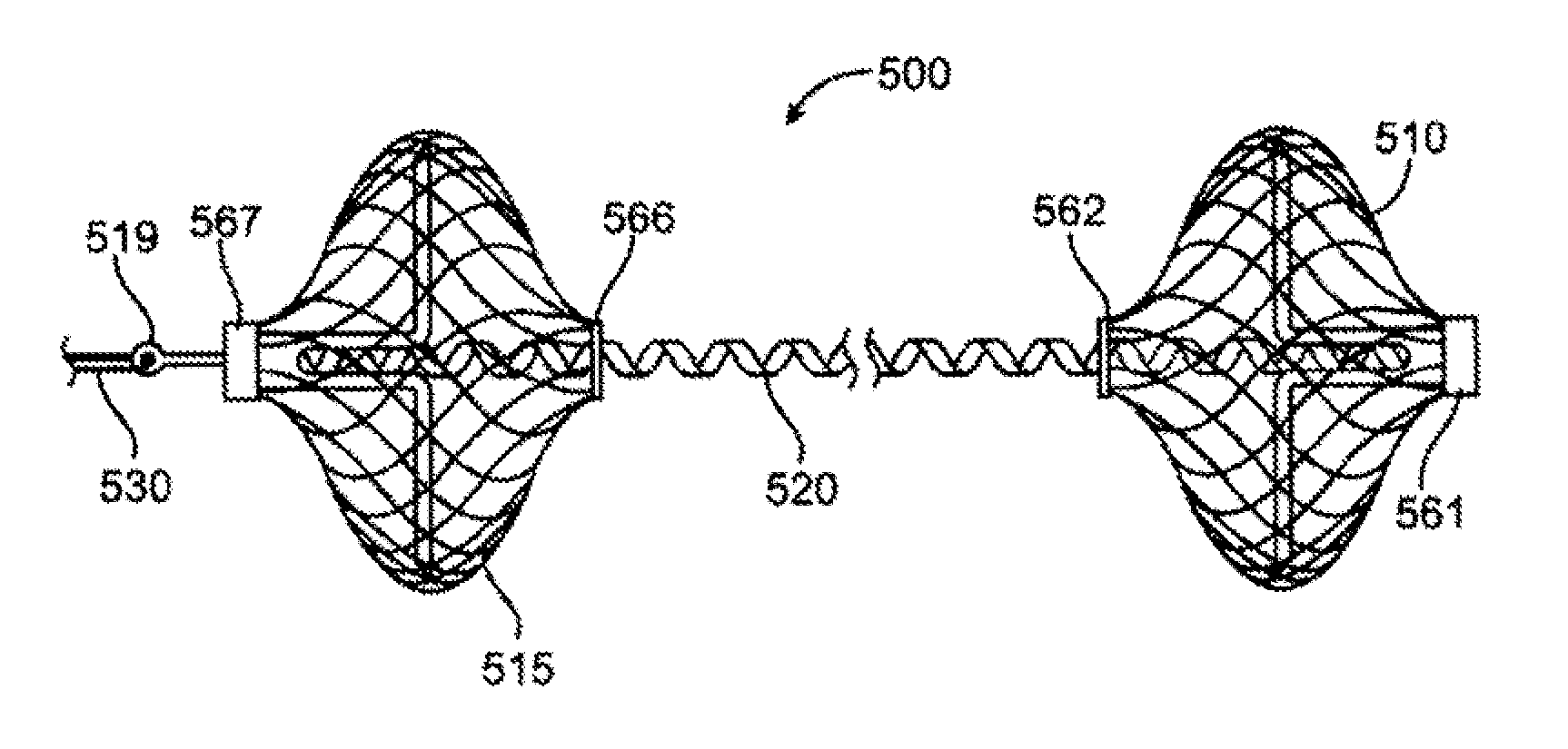
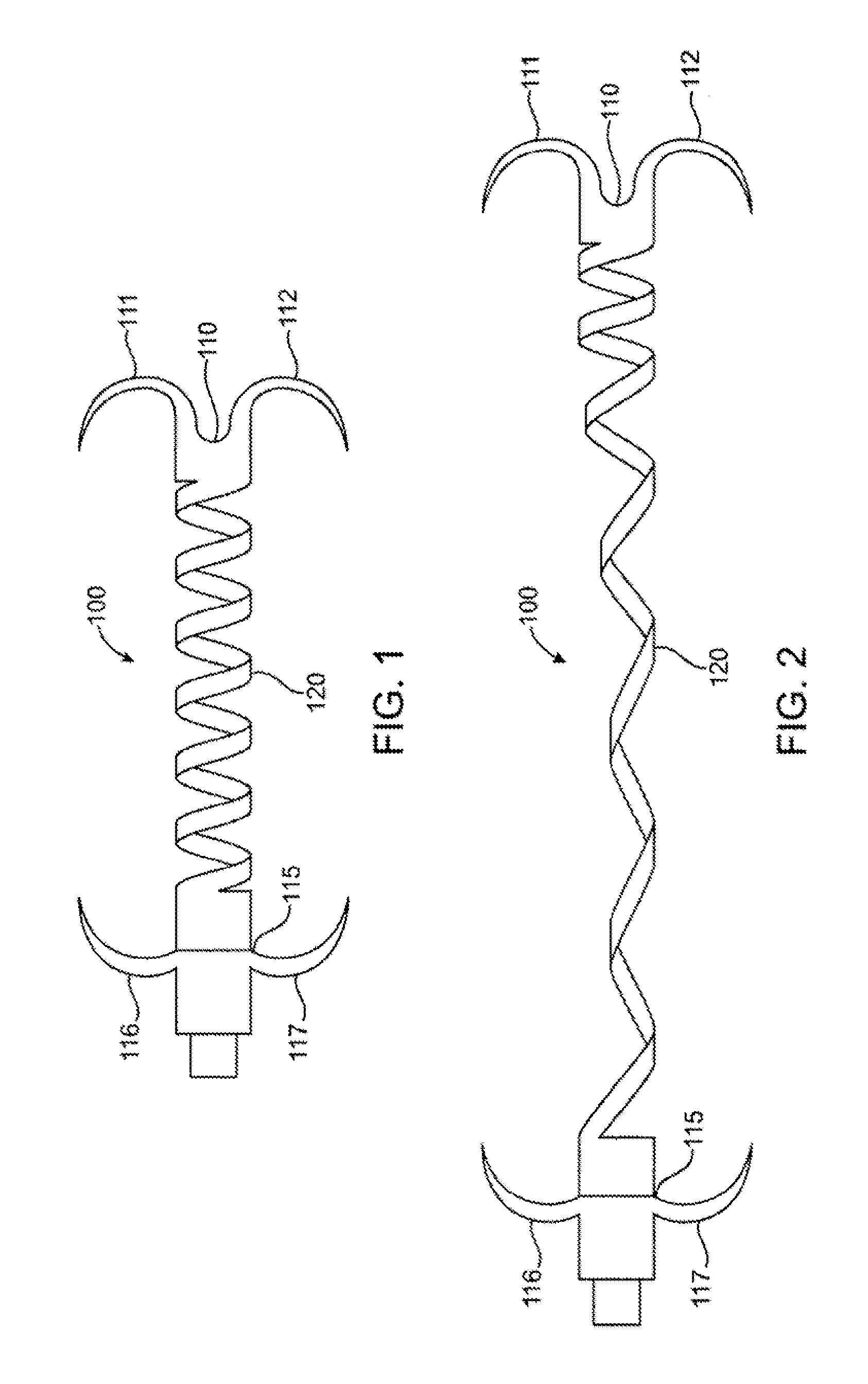
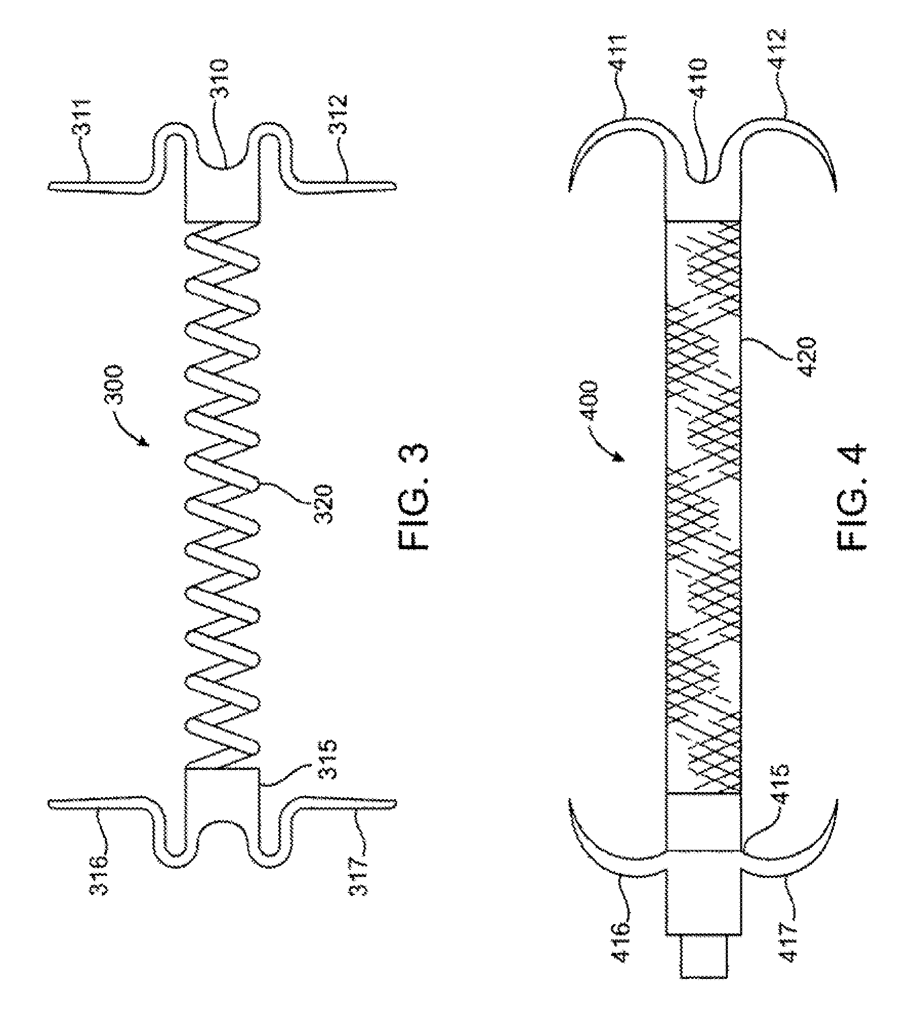
[0032] The invention will now be described in detail below by referring to the attached drawings, where like numbers refer to like structures. One aspect of the present invention is a device for treating mitral valve regurgitation by reducing the lateral space between the septal wall and the free wall of a heart chamber. One embodiment of a device, in accordance with the present invention, is illustrated in FIGS. 1 & 2, which show the device in a deployed / deployment configuration as opposed to a delivery configuration as depicted in FIG. 6.

[0033] Tensioning device 100 is designed to be positioned across a chamber of a heart so that it reduces the distance between the septum and the free wall of a heart chamber to alter the chamber geometry and wall tension thereby reducing valvular regurgitation. Although described below in the context of treating mitral valve regurgitation by reducing or limiting lateral distension of the left ventricle as the heart beats, device 100 may be deploy...


PUM


Abstract

A system for treating mitral valve regurgitation comprises tensioning device that can be deployed using a delivery catheter. The device includes tension member linking a proximal anchor and distal anchor. The device is constructed from a material having suitable elastic properties such that the device applies a constant tension force between the anchors, while stretching or flexing in response to a heartbeat when positioned across a chamber of a heart. The anchors may include a plurality of arms. In some embodiments, the arms may also flex in response to a heart beat. When positioned across the left ventricle of a heart, the device can reduce the lateral distance between the walls of the ventricle and thus allow better coaption of the mitral valve leaflets thereby reducing mitral regurgitation.

Description

PRIORITY CLAIM [0001] This application claims priority under 35 U.S.C. §119(e) from U.S. Provisional Application No. 60 / 713,299 filed Aug. 31, 2005; and U.S. Provisional Application No. 60 / 743,349, filed Feb. 24, 2006; the entirety of each of which is hereby incorporated by reference theretoTECHNICAL FILED [0002] This invention relates generally to medical devices and particularly to a system and method for treating mitral valve regurgitation. BACKGROUND OF THE INVENTION [0003] The heart is a four-chambered pump that moves blood efficiently through the vascular system. Blood enters the heart through the vena cava and flows into the right atrium. From the right atrium blood flows through the tricuspid valve and into the right ventricle, which then contracts and forces blood through the pulmonic valve and into the lung. Oxygenated blood returns from the lungs and enters the heart through the left atrium and pas s through the bicuspid mitral valve into the left ventricle. The left vent...

Claims


Application Information

Patent Timeline
IPC IPC(8): A61F2/02A61F2/24
CPCA61B17/00234A61B17/0401A61B17/0482A61F2/2487A61B2017/00867A61B2017/0443A61B2017/06052A61B2017/00243
Inventor RAFIEE, NASSERBLOOM, ELIOT F.GODAIRE, RAYMONDFINNEY, MICHAEL
Owner MEDTRONIC VASCULAR INC
Why Eureka
Try Eureka