Bifurcated peritoneal catheter
a peritoneal catheter and peritoneal cavity technology, applied in the field of bifurcated peritoneal catheters, can solve the problems of affecting millions of people's death, impurities that cannot be eliminated by the body, and buildup of impurities within the peritoneal cavity of the body, and achieve the effect of minimal turbulen
- Summary
- Abstract
- Description
- Claims
- Application Information
AI Technical Summary
Benefits of technology
Problems solved by technology
Method used
Image
Examples
first embodiment
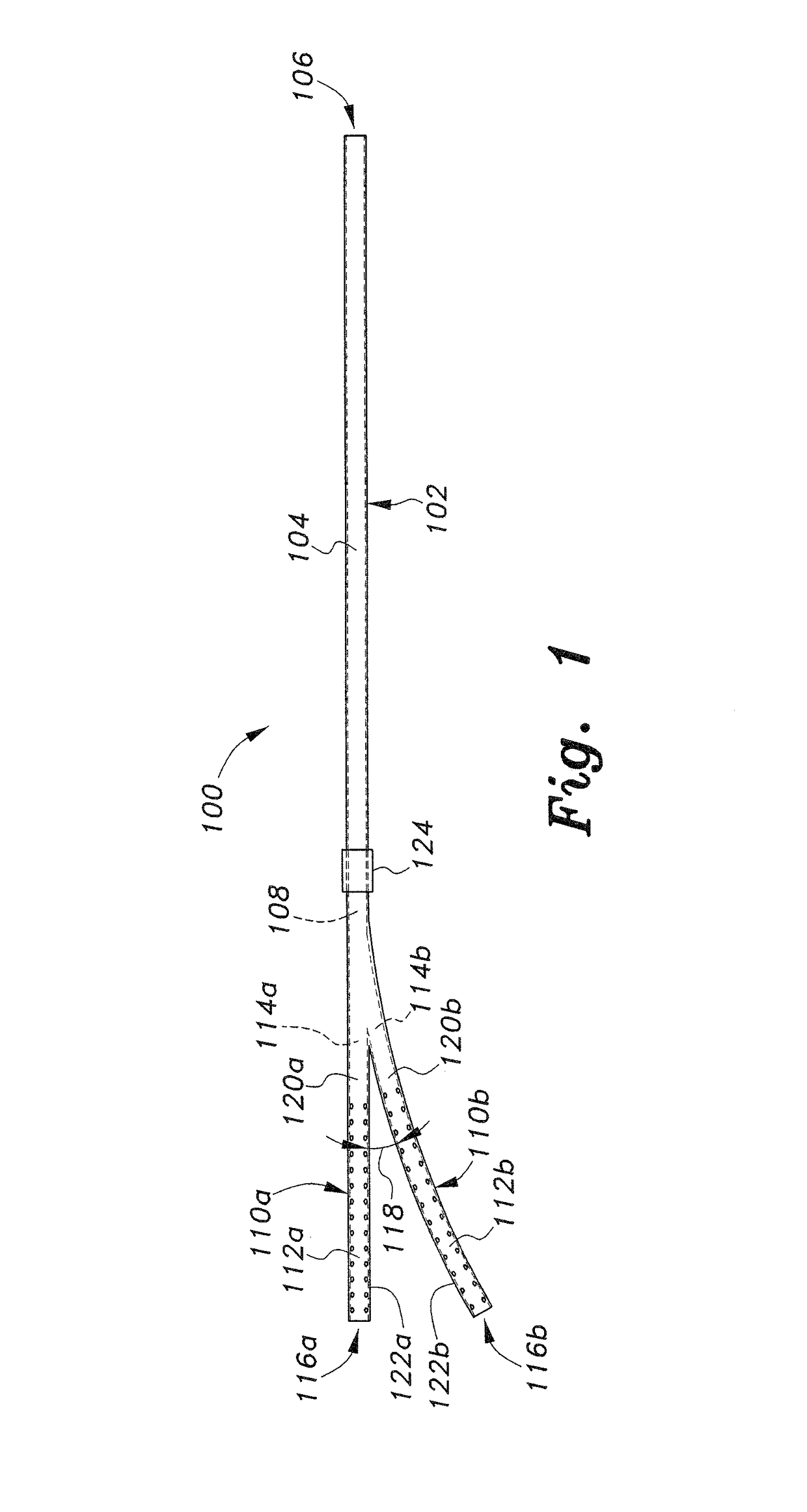
[0026]FIG. 1 of the drawings illustrates a top plan view of the bifurcated peritoneal catheter, designated as bifurcated peritoneal catheter (or catheter) 100. The catheter 100 includes a thin, elongate primary tube 102 having a closed wall 104 with an open proximal end 106 and an opposite open distal end 108. Some portion of the length of the primary tube 102 to the proximal end 106 thereof extends externally from the patient to appropriate fluid delivery and collection points external to the patient during the dialysis procedure. The distal end portion 108 of the primary tube 102 is surgically implanted within the patient.
[0027]First and second internal tubes, respectively 110a and 110b, are adapted for surgical placement within the peritoneal cavity of the patient. Each of these two internal tubes 110a, 110b comprise a long, thin element having a wall, respectively 112a and 112b, with an open proximal end, respectively 114a and 114b, and opposite open distal end, respectively 116...
second embodiment
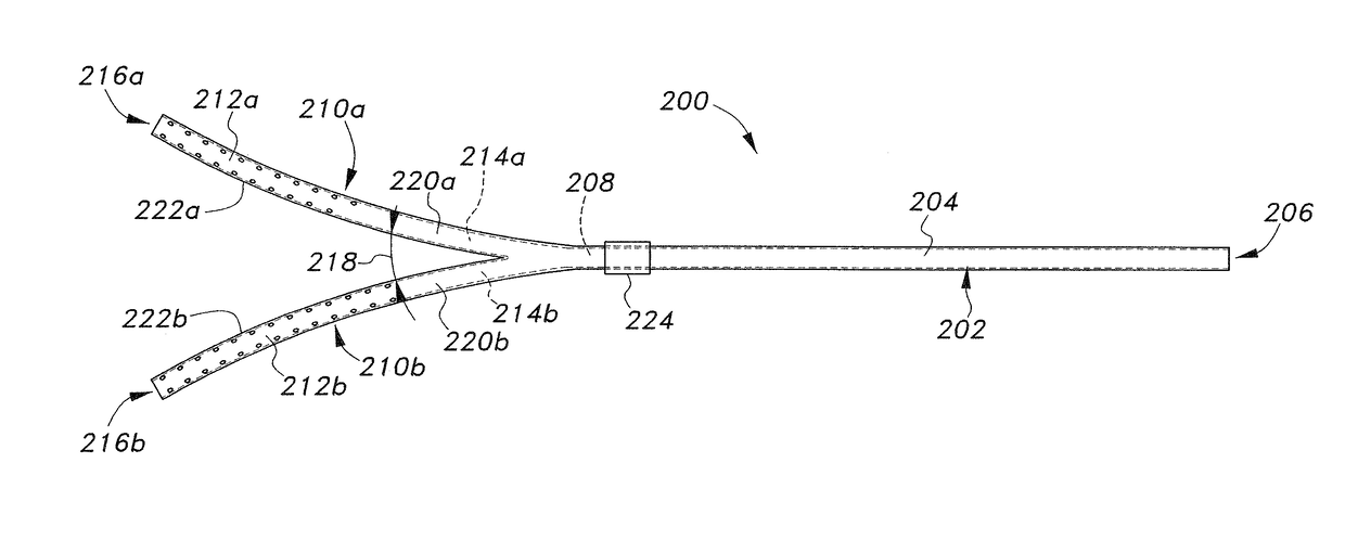
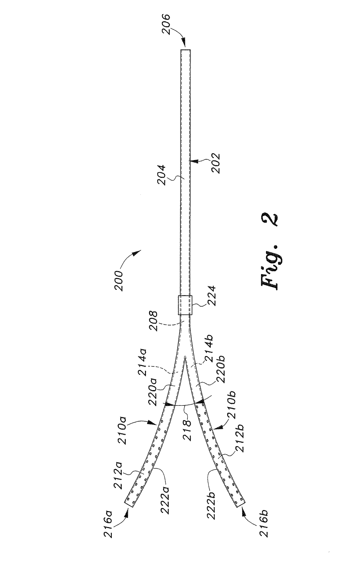
[0029]FIG. 2 of the drawings illustrates a second embodiment bifurcated peritoneal catheter 200. The catheter 200 is configured similarly to the catheter 100 of FIG. 1, i.e., having a thin, elongate primary tube 202 with a closed wall 204, open proximal end 206, and opposite open distal end 208. It will be seen that the length of the primary tube 202 is somewhat shorter than the length of the primary tube 102 of the catheter 100 of FIG. 1. The primary tube lengths of any of the bifurcated peritoneal catheters described herein, as well as their two internal catheters, can be formed or adjusted as desired.
[0030]First and second internal tubes, respectively 210a and 210b, are also adapted for surgical placement within the peritoneal cavity of the patient. These two internal tubes 210a, 210b each comprise a long, thin element having a wall, respectively 212a and 212b, with an open proximal end, respectively 214a and 214b, and opposite open distal end, respectively 216a and 216b. The pro...
embodiment 200
[0031]It will be noted in the catheter 200 example of FIG. 2 that both of the internal tubes 210a and 210b are curved away from one another. This, and the shorter length of the primary tube 202, is the primary distinction between the bifurcated peritoneal catheter embodiment 100 of FIG. 1 and the embodiment 200 of FIG. 2.
[0032]FIG. 3 of the drawings illustrates a third embodiment 300 of the bifurcated peritoneal catheter. The catheter 300 is configured similarly to the catheter 100 of FIG. 1, i.e., having a thin, elongate primary tube 302 with a closed wall 304, open proximal end 306, and opposite open distal end 308. First and second internal tubes, respectively 310a and 310b, extend from the distal end 308 of the primary tube 302, with the first and second internal tubes each comprising a long, thin element having a wall, respectively 312a and 312b, an open proximal end, respectively 314a and 314b, and opposite open distal end, respectively 316a and 316b. The proximal ends 314a, 3...
PUM
 Abstract
Description
Claims
Application Information
 - R&D
- Intellectual Property
- Life Sciences
- Materials
- Tech Scout
- Unparalleled Data Quality
- Higher Quality Content
- 60% Fewer Hallucinations
Browse by: Latest US Patents, China's latest patents, Technical Efficacy Thesaurus, Application Domain, Technology Topic, Popular Technical Reports.
© 2025 PatSnap. All rights reserved.Legal|Privacy policy|Modern Slavery Act Transparency Statement|Sitemap|About US| Contact US: help@patsnap.com


