
System and methods for motorized injection and aspiration

a motorized injection and aspiration technology, applied in the field of motorized injection and aspiration, can solve the problems of inability to change parameters in real time during injection or aspiration, inability to enable aspiration and/or delivery of the same tissue or liquid, and inability to achieve aspiration and/or aspiration. , to achieve the effect of preventing contamination, reducing waste of precious and expensive reagents, and reducing turbulence and physical disturban

Inactive Publication Date: 2017-08-29
ABDULREDA MIDHAT H +2
View PDF32 Cites 0 Cited by
  • Summary
  • Abstract
  • Description
  • Claims
  • Application Information

AI Technical Summary

Benefits of technology

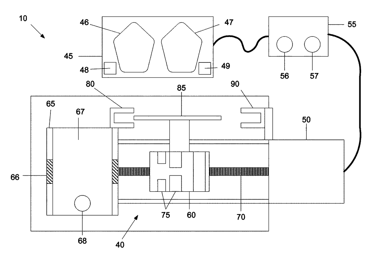
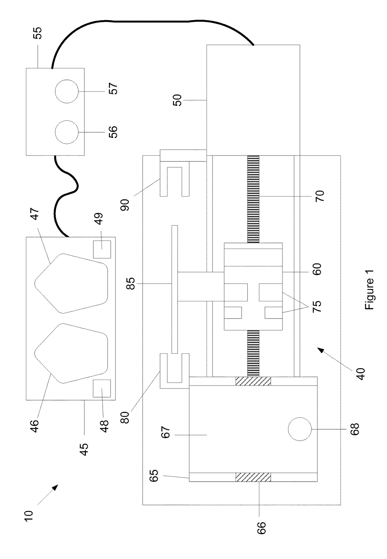
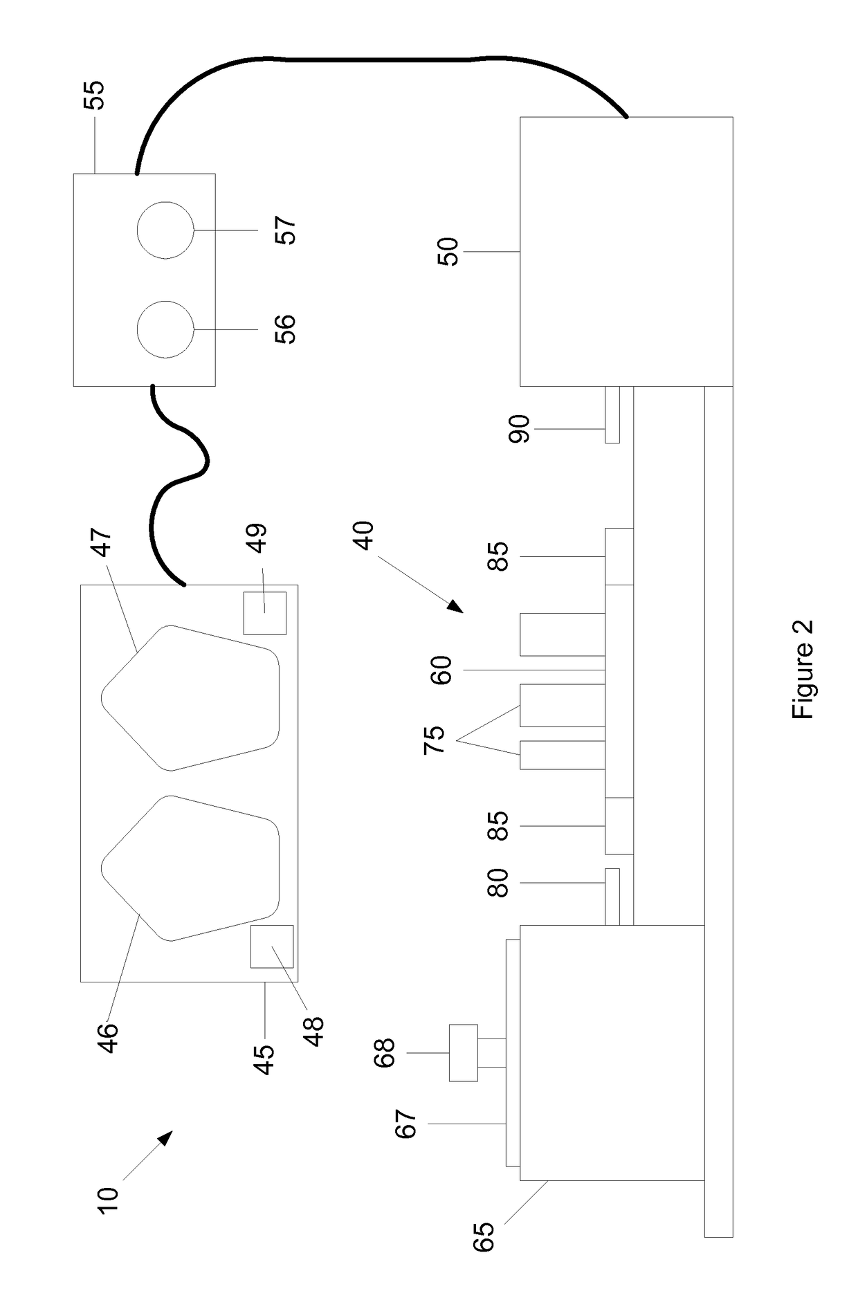
[0005]The present invention provides a motorized injection and aspiration system that allows for an immediate transition between the actions of injection and aspiration through a single entry point without interruption at any time during the operation and as many times as desired through the use of one or more foot pedals. The motorized injection and aspiration system has the additional benefit of adjusting the flow rate and volume of working fluid to be aspirated or injected via the same one or more foot pedals. This system accomplishes controlled and precise aspiration and delivery of solutions of macro- and micro-particles into confined spaces with minimal turbulence and physical disturbance, which in turn reduces the waste of precious and expensive reagents. Yet another improvement of the system is that the components in contact with the specimen and the solution are autoclavable to prevent contamination in sterile applications. A further advantage of the system is that in operation it is hands-free, enabling a single person to perform procedures, such as transplantations, which are typically performed by two people.

Problems solved by technology

These systems require the user to stop / pause in the middle of a procedure and let go of the specimen or animal, when this may not be possible or desirable, in order to reprogram the control unit to switch modes.
Further, reprogramming the control unit in the middle of a procedure is impractical since the operator's hands are typically not free.
Moreover, while these systems can deliver preset volumes at preset flow rates, these parameters cannot be changed in real time during injection or aspiration.
As a result, these systems do not enable aspiration and / or delivery of the same tissue or liquid.

Method used


Image

  • System and methods for motorized injection and aspiration
  • System and methods for motorized injection and aspiration
  • System and methods for motorized injection and aspiration

Examples


examples

[0069]Presented below, is a new approach combining intraocular transplantation and confocal microscopy enables longitudinal, non-invasive real-time imaging with single-cell resolution within grafted tissues in vivo. This demonstrates how to transplant pancreatic islets into the anterior chamber of the mouse eye.

[0070]Advances in intravital microscopy have revealed physiological phenomena not predicted by in vitro studies (Weigert et al., 2010). This highlights the challenge in translating findings obtained by conventional in vitro methods into the living animal. In the last decade, visualization of tissues in living animals was considerably improved by technological advances in imaging modalities (reviewed in (Aswathy et al., 2010; Ghoroghchian et al., 2009; Leibiger et al., 2011; Ntziachristos, 2010; Wang et al., 2010b)). This has spurred a need for in vivo imaging approaches with feasible application in experimental animal models to enable non-invasive visualization of target tiss...


PUM


Abstract

A motorized injection and aspiration system and methods for its use, where the motorized injection and aspiration system comprises (a) a syringe coupled to a needle, wherein the syringe includes a plunger, (b) a cannula, (c) a tube having first and second ends, wherein the first end is coupled to the needle and the second end is coupled to the cannula, (d) a syringe driver to drive the plunger, (e) at least one foot pedal, (f) a step motor, and (g) a control unit in communication with the step motor, the syringe driver and the at least one foot pedal.

Description

CROSS-REFERENCE[0001]This application claims priority to U.S. Provisional Patent Application Ser. No. 61 / 485,793 filed May 13, 2011 and 61 / 534,516 filed Sep. 14, 2011, each of which is incorporated by reference herein in its entirety.STATEMENT OF U.S. GOVERNMENT INTEREST[0002]This invention was made with government support under Grant Nos. F32DK083226 and 5U01DK070460-07 awarded by the National Institutes of Health. The U.S. government has certain rights in the invention.BACKGROUND OF THE INVENTION[0003]Micro-procedures, such as micro-surgery or micro-manipulation, in experimental and / or clinical settings at times require both injection and aspiration of fluids or solutions. Currently available syringe pumps work either in a single injection or aspiration mode. These systems require the user to stop / pause in the middle of a procedure and let go of the specimen or animal, when this may not be possible or desirable, in order to reprogram the control unit to switch modes. Further, repr...

Claims


Application Information

Patent Timeline
Patent Type & Authority Patents(United States)
IPC IPC(8): A61M5/20A61M5/145A61M1/00A61M5/31A61B17/00
CPCA61M5/1456A61M1/0058A61M5/1458A61M5/3148A61B2017/00973A61B2017/00977A61M1/0062A61M2205/586A61M2209/01A61M1/772A61M1/77A61M5/145A61M1/00A61M5/31
Inventor ABDULREDA, MIDHAT H.BERGGREN, PER-OLOFFREITES, CONRADO
Owner ABDULREDA MIDHAT H
Learn More