Air flow system for waste treatment systems

a waste treatment system and air flow technology, applied in the direction of machines/engines, transportation and packaging, liquid fuel engines, etc., can solve the problems of waste items losing traction, suboptimal system performance or even malfunction, and limited speed of conveyor belts, etc., to achieve a large surface area, increase speed, and increase speed

Active Publication Date: 2020-05-07
BOLLEGRAAF PATENTS & BRANDS
View PDF0 Cites 0 Cited by
  • Summary
  • Abstract
  • Description
  • Claims
  • Application Information

AI Technical Summary

Benefits of technology

[0009]According to the present invention, when the air flow system is in operation the divergent channel of each air flow unit enclosure provides a stream of air over/to waste items arranged on the conveyor surface, wherein the stream of air has a velocity component which is substantially parallel to the conveyor surface and has a magnitude which is substantially equal to a speed of the conveyor surface. This allows waste items on the conveyor surface to move in unison therewith at much greater speeds whilst experiencing no discernibly air resistance as the stream of air expelled by the channel discharge end of each divergent channel moves in unison with the waste items and conveyor surface.
[0010]By allowing the widening cross section of the divergent channel to change

Problems solved by technology

However, in many cases the transport speed of conveyor belts is limited as contact of the waste items with conveyor belts may be lost due to air resistance, leading to suboptimal system performance or even malfunction.
Loss of tra

Method used


Image

  • Air flow system for waste treatment systems
  • Air flow system for waste treatment systems

Examples


embodiment 1

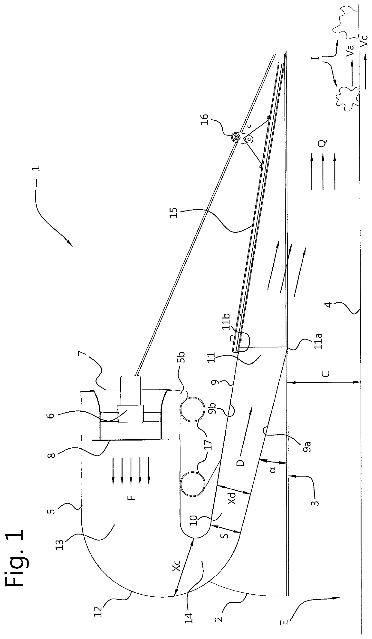
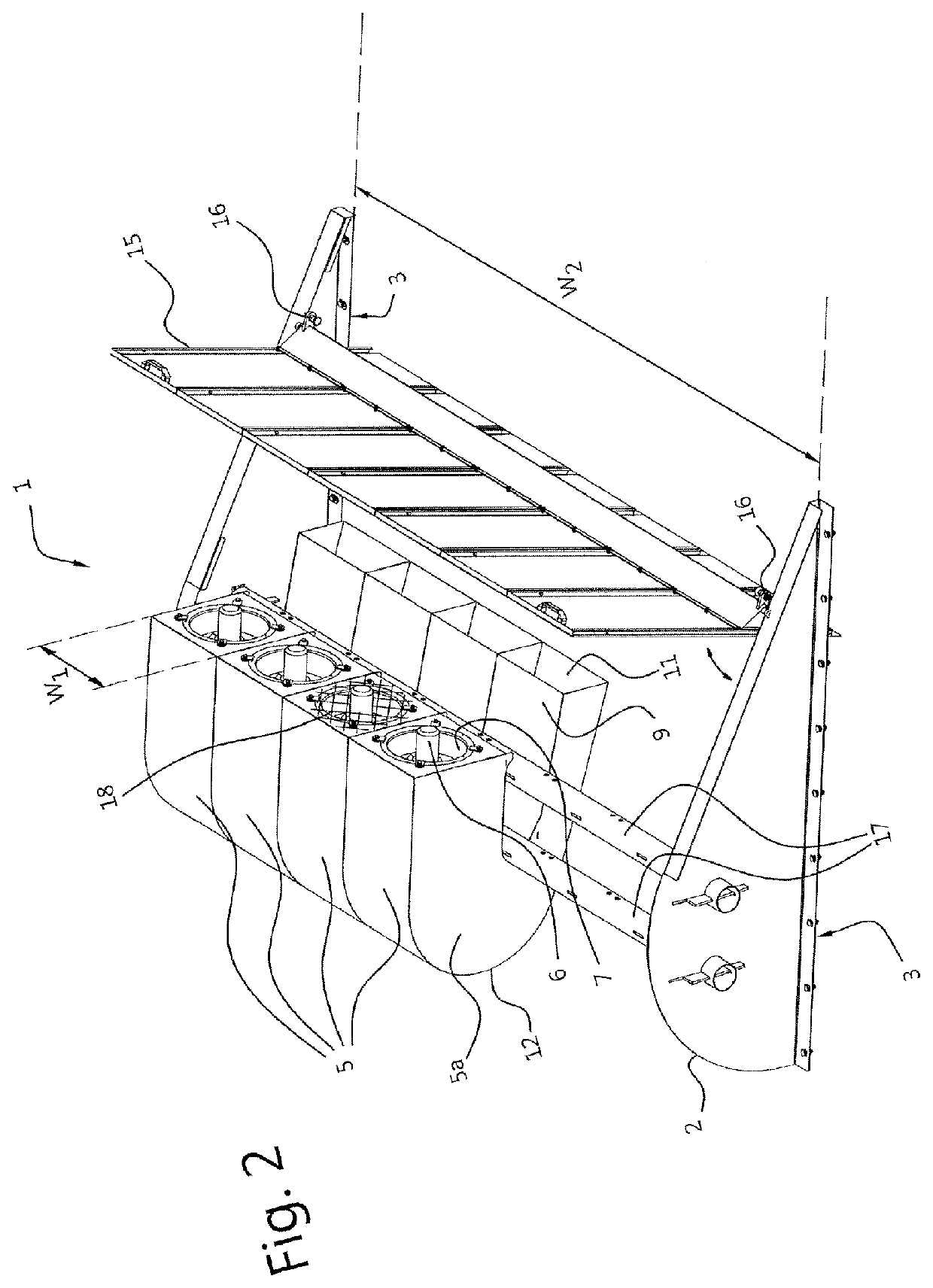
[0046]An air flow system (1) for a waste conveyor, comprising a conveyor enclosure (2) having a bottom side (3) configured for being mounted above a conveyor surface (4) at a predetermined surface clearance (C);

[0047]one or more air flow unit enclosures (5) mounted to the conveyor enclosure (2), wherein each airflow unit enclosure (5) comprises an airflow unit (6) having an air intake (7) and air exhaust (8),

[0048]wherein each airflow unit enclosure (5) comprises a divergent channel (9) having a channel intake end (10) fluidly connected to the air exhaust (8) and a channel discharge end (11) configured for providing a stream of air (Q) toward the conveyor surface (4),

[0049]wherein the divergent channel (9) comprises a widening cross section (Xd) in a downstream air direction (D) between the channel intake end (10) and the channel discharge end (11) of the divergent channel (9), and wherein the divergent channel (9) is arranged at an angle (α) larger than 0° and smaller than 45° degr...

embodiment 2

[0050]The air flow system according to embodiment 1, wherein the divergent channel (9) is a straight divergent channel.

embodiment 3

[0051]The air flow system according to embodiment 1 or 2, wherein each air flow unit enclosure (5) further comprises a convergent channel (12) having a channel intake end (13) fluidly connected to the air exhaust (8) and a channel discharge end (14) connected to the channel intake end (10) of the divergent channel (9),

[0052]wherein the channel intake end (10) of the divergent channel (9) comprises a smallest cross section (S) of the convergent channel (12) and divergent channel (9).


PUM


Abstract

An airflow system for a waste conveyor, having a conveyor enclosure with a bottom side configured for being mounted above a conveyor surface. One or more air flow unit enclosures are mounted to the conveyor enclosure. Each air flow unit enclosure has a divergent channel with a channel intake end fluidly connected to the air exhaust and a channel discharge end configured for providing a stream of air (Q) toward the conveyor surface. The divergent channel has a widening cross section (Xd) in a downstream air direction (D) between the channel intake end and the channel discharge end of the divergent channel, and is arranged at an angle (α) larger than 0° and smaller than 45° degrees with respect to the bottom side of the conveyor enclosure.

Description

FIELD OF THE INVENTION[0001]The present invention relates to an air flow system for waste treatment systems, in particular a laminar flow system for waste conveyance. In a further aspect the present invention relates to a method of waste conveyance.BACKGROUND ART[0002]Prior art waste handling and sorting systems may utilize conveyor belts for transporting waste items from one location to another. However, in many cases the transport speed of conveyor belts is limited as contact of the waste items with conveyor belts may be lost due to air resistance, leading to suboptimal system performance or even malfunction. Loss of traction on waste items is particularly problematic for light weight waste items such as plastic or paper waste items. As the transport speed of waste items is limited, overall system capacities and throughput remains limited as well.[0003]International patent publication WO03 / 61858 discloses a method and apparatus for identifying and sorting objects, such as (plastic...

Claims


Application Information

Patent Timeline
IPC IPC(8): B65G21/20B65G53/58
CPCB65G21/209B65G53/58B65G21/20F04D29/547F04D19/002F04D25/166F04D29/703F05D2250/52B65G53/44
Inventor BOERHOF, HENKVOGELAAR, JOHANNES SIJBRAND
Owner BOLLEGRAAF PATENTS & BRANDS
Why Eureka
Try Eureka