Dynamic damper assembly

a technology of damper and assembly, which is applied in the direction of spring/damper functional characteristics, shock absorbers, mechanical devices, etc., can solve the problems of deteriorating accuracy or the risk of malfunction, and affecting the nvh of the vehicle. , to achieve the effect of suppressing the increase in weight and cost and improving the nvh of the vehicl

Active Publication Date: 2017-09-21
HYUNDAI MOTOR CO LTD
View PDF0 Cites 2 Cited by
  • Summary
  • Abstract
  • Description
  • Claims
  • Application Information

AI Technical Summary

Benefits of technology

[0012]Various aspects of the present invention are directed to providing a dynamic damper assembly capable of improving NVH of a vehicle and suppressing increases in weight and cost by attenuating a secondary anti-resonance due to the attenuation of a multi-frequency or by simultaneously primary and secondary bending modes, even by only one damper.
[0022]As apparent from the above description, in accordance with the dynamic damper assembly, the conventional integrated heavy body is divided into a plurality of pieces so that these pieces have different masses, and the resultant of the centrifugal forces of the respective heavy bodies is set to be “0”. Thereby, it is possible to realize the dynamic damper assembly having an attenuation effect on multi-frequency by eliminating rotating unbalance.
[0023]Accordingly, it is possible to further improve NVH of the vehicle by attenuating the secondary anti-resonant region caused due to attenuation by the conventional dynamic damper. In addition, it is possible to control the resonance due to the primary bending mode of the drive shaft and various responses in the peripheral system of secondary anti-resonance before and after the bending mode. In addition, it is possible to reduce weight and costs compared to methods of additionally mounting dynamic dampers in order to improve NVH.

Problems solved by technology

For example, when an external force is applied to a device for generating power by transferring explosive power from a four-stroke engine of a vehicle to drive wheels through drive shafts via a transmission, or a structure which does not have its own power, vibrations occur in the device or the structure.
These vibrations deteriorate the mounting safety of the engine or structure, and cause interference when the components or related parts thereof are operated, which may lead to the deterioration of accuracy or the risk of malfunction.
For this reason, the drive shafts cause bending vibrations such as torsion and whirling, and the explosive vibration of the engine is applied to the drive shafts.
However, there is a limit to the attenuation of anti-resonance using such materials, and a desired frequency may be offset in a low-temperature region (at a temperature equal to or less than 0° C., or in a cold region) since the rate of change in natural frequency is increased according to a change in temperature.
In addition, two dynamic dampers may be mounted to a vehicle in which a considerable degree of secondary anti-resonance occurs, but this is disadvantageous in terms of increases in weight and cost.

Method used


Image

  • Dynamic damper assembly
  • Dynamic damper assembly
  • Dynamic damper assembly

Examples


Embodiment Construction

[0032]Reference will now be made in detail to various embodiments of the present invention(s), examples of which are illustrated in the accompanying drawings and described below. While the invention(s) will be described in conjunction with exemplary embodiments, it will be understood that the present description is not intended to limit the invention(s) to those exemplary embodiments. On the contrary, the invention(s) is / are intended to cover not only the exemplary embodiments, but also various alternatives, modifications, equivalents and other embodiments, which may be included within the spirit and scope of the invention as defined by the appended claims.

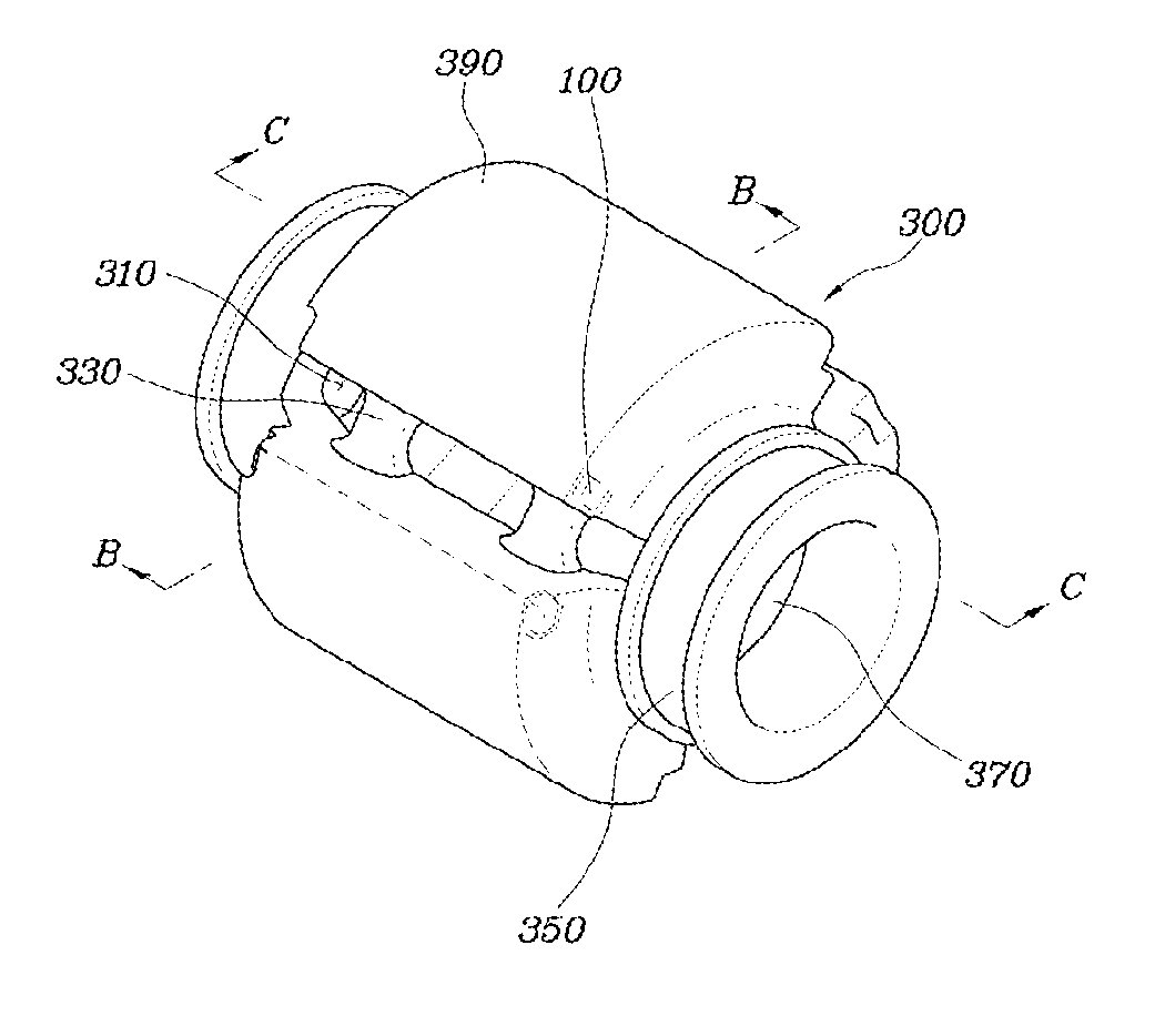
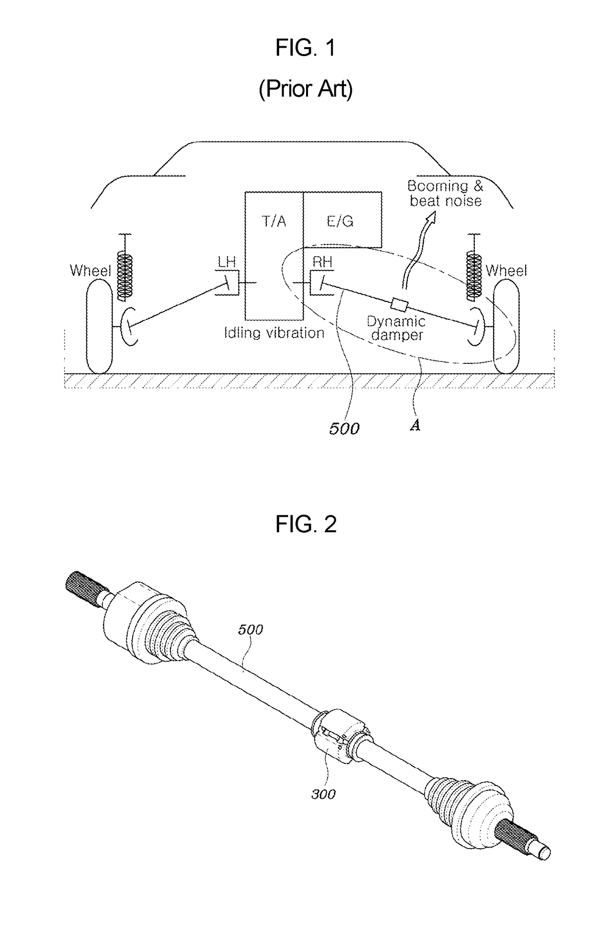
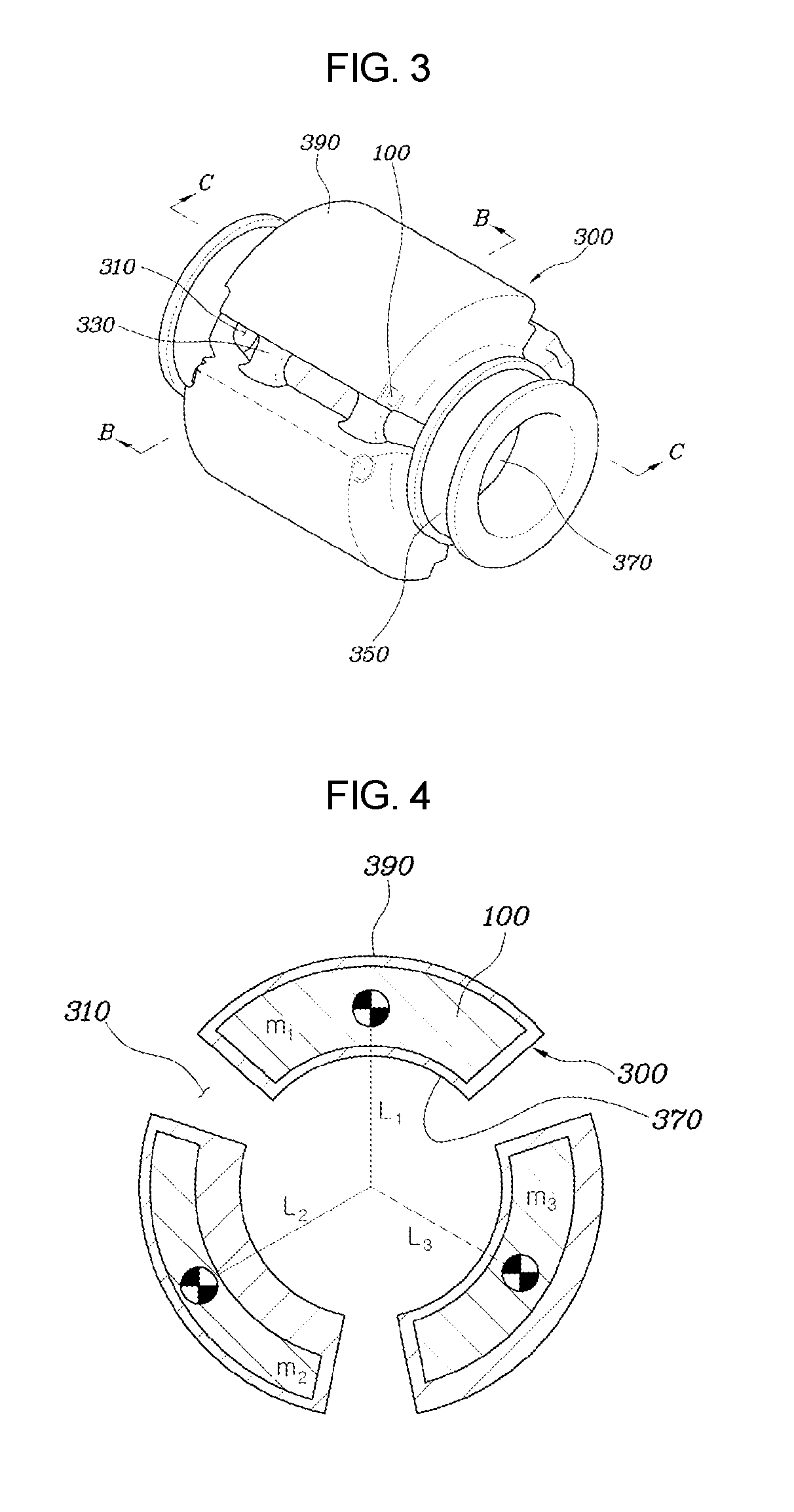
[0033]FIG. 1 is a view schematically illustrating a structure of a typical vehicle. FIG. 2 is an enlarged view illustrating portion “A” of FIG. 1, and is a view illustrating a state in which a dynamic damper assembly is mounted to a drive shaft 500 according to various embodiments of the present invention. FIG. 3 is a view illustr...


PUM

PropertyMeasurementUnit
temperatureaaaaaaaaaa
elasticaaaaaaaaaa
radial thicknessesaaaaaaaaaa

Abstract

A dynamic damper assembly may include a plurality of bodies arranged at predetermined intervals on an outer peripheral surface of a drive shaft, and an elastic body formed to surround each of the bodies and fixing each body to the drive shaft.

Description

CROSS REFERENCE TO RELATED APPLICATION[0001]The present application claims priority to Korean Patent Application No. 10-2016-0033391, filed Mar. 21, 2016, the entire contents of which is incorporated herein for all purposes by this reference.BACKGROUND OF THE INVENTION[0002]Field of the Invention[0003]The present invention relates to a dynamic damper provided in a drive shaft of a vehicle to reduce booming noise occurring when a bending mode of the drive shaft coincides with an excitation frequency of an engine, and, more particularly, to a dynamic damper assembly capable of reducing noise in a multi-frequency band even though only one dynamic damper is mounted to a drive shaft.[0004]Description of Related Art[0005]In general, vibrations occur in a structure or a device when an external force is applied thereto, regardless of whether the structure or the device has or does not have its own power.[0006]For example, when an external force is applied to a device for generating power by...

Claims


Application Information

Patent Timeline
Patent Type & Authority Applications(United States)
IPC IPC(8): F16F15/14F16F7/108
CPCF16F15/1435F16F2228/04F16F2232/02F16F7/108F16F15/136F16F15/14F16F15/22F16F7/104F16F15/1414
Inventor KIM, HYUN SICK
Owner HYUNDAI MOTOR CO LTD
Why Eureka
Try Eureka