Assembly for Blocking and Enabling a Shifting Position of a Shifting Element

a technology of shifting element and assembly, which is applied in the direction of mechanical equipment, preventing unauthorised/accidental actuation, and operating means/releasing devices of valves, etc., can solve the problems of large installation space required by the mechanism, high loss of rotary feedthrough, and not being neutral in weight or cos

Active Publication Date: 2017-09-21
ZF FRIEDRICHSHAFEN AG
View PDF1 Cites 1 Cited by
  • Summary
  • Abstract
  • Description
  • Claims
  • Application Information

AI Technical Summary

Benefits of technology

[0003]Exemplary aspects of the present invention provide an arrangement for locking and releasing a shifting position of a shifting element, which is integrated into an existing shift element that is as neutral in terms of installation space and weight as is possible, and can be controlled independently of the actuating pressure.

Problems solved by technology

At high clutch pressures during the shifting of the clutch, such rotary feedthroughs experience high losses due to leakages.
However, such locking mechanisms require a large amount of installation space, and are thus not neutral either in terms of weight or cost.

Method used


Image

  • Assembly for Blocking and Enabling a Shifting Position of a Shifting Element
  • Assembly for Blocking and Enabling a Shifting Position of a Shifting Element
  • Assembly for Blocking and Enabling a Shifting Position of a Shifting Element

Examples


Embodiment Construction

[0029]Reference will now be made to embodiments of the invention, one or more examples of which are shown in the drawings. Each embodiment is provided by way of explanation of the invention, and not as a limitation of the invention. For example, features illustrated or described as part of one embodiment can be combined with another embodiment to yield still another embodiment. It is intended that the present invention include these and other modifications and variations to the embodiments described herein.

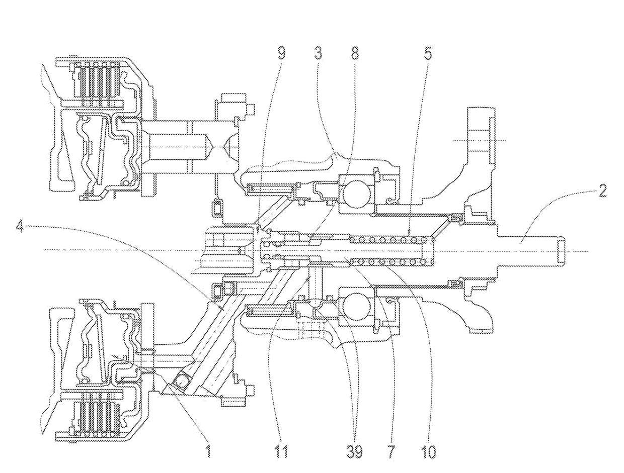
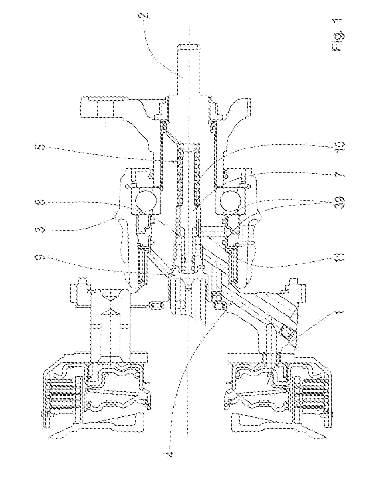
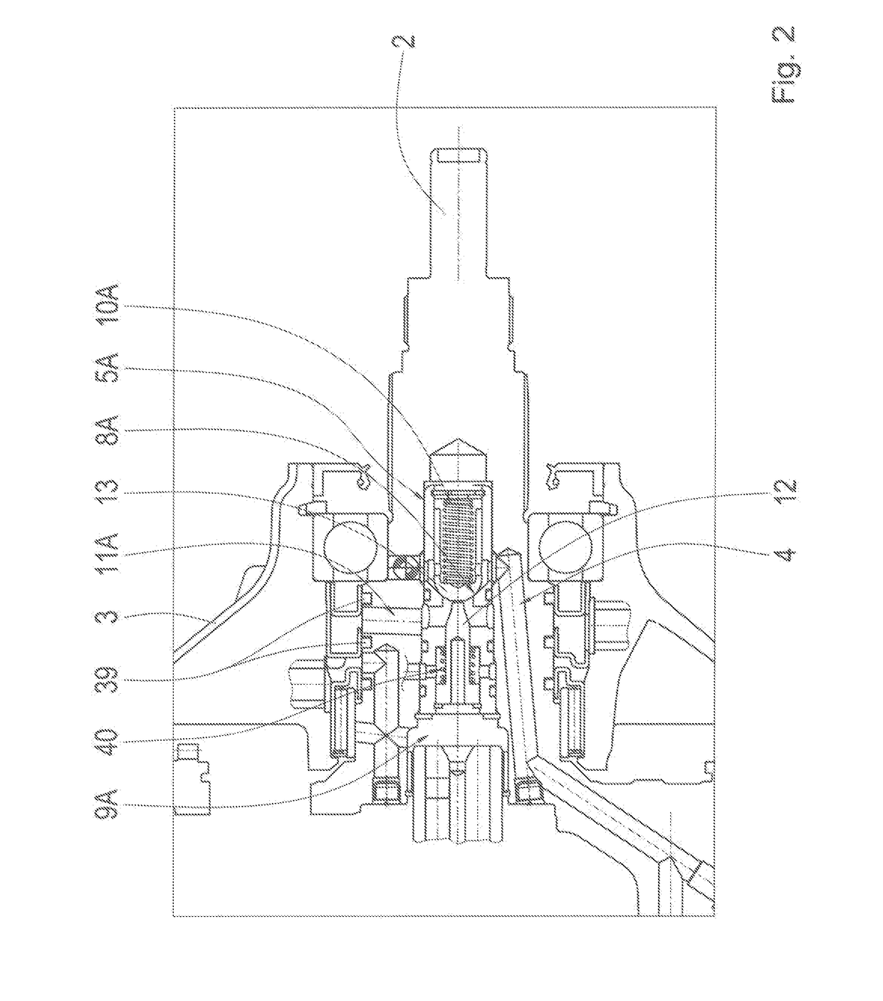
[0030]FIGS. 1 to 11A present examples of the proposed arrangement in accordance with example aspects of the invention on the basis of various design variants and embodiments. The arrangement includes at least one shifting element that can be actuated hydraulically by an actuating pressure, for example as a clutch 1, 1A, which is arranged coaxially at or on at least one transmission shaft 2 in a transmission housing 3 of an automatic transmission of a vehicle. Furthermore, the arra...


PUM


Abstract

A system for locking and releasing a shifting position of a shifting element that is hydraulically actuatable by an actuating pressure is provided. The shifting element is arranged coaxially with a transmission shaft. The system includes a stop valve. The stop valve is subjectable to a control pressure that is separate from the actuating pressure of the shifting element. The stop valve is arranged radially inside the shifting element in the transmission housing.

Description

FIELD OF THE INVENTION[0001]The present invention relates generally to an arrangement for locking and releasing a shifting position of a shifting element that can be actuated hydraulically with actuating pressure, in a transmission housing arranged coaxially at a transmission shaft.BACKGROUND[0002]Shifting elements, such as clutches or the like in automatic transmissions, as known from DE 198 58 541 A1, are typically kept closed by hydraulically actuated pistons with corresponding actuation pressure in the clutch cylinder. The pressurized oil is guide in the transmission housing to the clutch cylinder or to the clutch piston by rotating elements, which are sealed by gap seals, for example slide bearings or rectangular rings. At high clutch pressures during the shifting of the clutch, such rotary feedthroughs experience high losses due to leakages. In order to prevent leakage losses for closed (that is, actuated) shifting elements or clutches, locking mechanisms controlled depending ...

Claims


Application Information

Patent Timeline
Patent Type & Authority Applications(United States)
IPC IPC(8): F16H61/00F16K35/06F15B13/01F16K31/122F16H61/30F16H63/30
CPCF16H61/0021F16H61/30F16K35/06F15B13/01F16K31/1221F16H63/3026F16K31/122F16H2710/00F16H61/0276F16H2061/0279
Inventor ZIEMER, PETERHAUPT, JOSEFMARGRAF, CHRISTOPHHERRMANN, MARKUSSCHMIDT, THILODOERR, ULRICHSIBLA, CHRISTIANBECK, STEFANWIESNER, MAIKBROM, STEFAN
Owner ZF FRIEDRICHSHAFEN AG
Why Eureka
Try Eureka