Lighting device and lighting system

a lighting device and lighting technology, applied in lighting and heating devices, semiconductor devices for light sources, instruments, etc., can solve the problem of no significant effect on the overall cost-price of lighting devices, and achieve the effects of reducing spill light, increasing the versatility of dynamic lighting possibilities, and relatively compact lighting devices

Active Publication Date: 2017-09-21
SIGNIFY HLDG BV
View PDF7 Cites 4 Cited by
  • Summary
  • Abstract
  • Description
  • Claims
  • Application Information

AI Technical Summary

Benefits of technology

[0010]With increasing number of rings shaped deflective portions the versatility of dynamic lighting possibilities is increased as the number of directions into which said incident light can be directed is increased by each ring. Therefore, the number of rings preferably is at least four, for example five, eight, nine, sixteen or seventeen. The ring can have a round, circular shape, or can have the shape of a relatively high numbered regular polygon having a shape quite similar to a round circle, for example a hexagon, octagon, decagon or dodecagon.
[0011]Because the fixed deflective member is positioned in between the light source and the fixed deflective member, it is thus enabled to position the fixed deflective member directly opposite, close to the light source. Thus easy alignment of the deflective portions with a respective lighting element is enabled, furthermore spill light and the risk of cross-over between adjacent combinations of reactive portions and lighting elements are counteracted. It is further preferable that the rotatable deflective member is positioned close to fixed deflective member, yet without being in optical contact therewith, to further reduce spill light and to enable the manufacture of a relatively compact lighting device. Alternatively it is possible to position the rotatable deflective member in between the light source and the fixed deflective member. However, due to the rotation of the rotatable deflective member deflected light by the rotatable deflective member, for a single lighting element the effect will occur of impingement on a variable location on the fixed deflective member, thus requiring a more complex arrangement of deflective portions on the fixed deflective member. Yet, this effect can be significantly reduced by positioning the fixed deflective member directly adjacent to the rotatable deflective member along the central axis. This effect is generally no issue in the case of the fixed member being positioned in between the light source and the rotatable deflective member, as the refractive structure on a main surface of the rotatable deflective member is in general the sa

Problems solved by technology

Yet, in view of the trends in cost-price of LEDs in the direction of “LEDs for free”, the a

Method used


Image

  • Lighting device and lighting system
  • Lighting device and lighting system
  • Lighting device and lighting system

Examples


Embodiment Construction

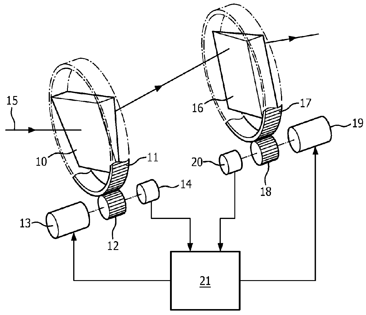
[0031]FIG. 1 shows a lighting device according to the prior art in which a first, rotatable prism 10 is mounted in a carrier 11, part only of which is shown. The carrier is arranged to be rotatable about a central axis 15 and is formed with a toothed gearing for cooperation with a pinion 12. The pinion is connected to a first motor 13 and a synchro resolver 14. A second rotatable prism 16 is located adjacent to the first prism so that it intercepts the beam of radiation leaving the first prism. The planes bisecting the apex angles of prisms 10 and 16 are arranged to be approximately normal to the central axis 15 about which the carriers rotate. The second prism is also mounted in a carrier 17 which is rotatable, and carries a toothed gear ring for engagement with a pinion 18 driven by a second motor 19. A second synchro resolver 20 is also connected to the second drive motor. Rotation of the two prisms about the central axis is possible quite independently of one another, whilst ret...


PUM


Abstract

A lighting device comprises a light source defining a central axis and comprising at least two mutually independently operable lighting elements. The lighting device further comprises a rotatable deflective member rotatably mounted about said axis, and a fixed deflective member fixedly mounted on said axis and comprising at least two mutually differently deflective portions which each are associated with a respective lighting element. The lighting device of the invention enables various operation modes, like light beam rotation can rotate, jumping of the light beam from one location to another by a sequence of switching on and off one or more of the at least two lighting elements, or in that it can be dimmed or boosted, for example dimmable in steps by a sequence of one by one switching off the lighting elements.

Description

FIELD OF THE INVENTION[0001]The invention relates to a lighting device comprising a rotatable deflective member and to a lighting system comprising such a lighting device and a control unit.BACKGROUND OF THE INVENTION[0002]Lighting devices and lighting systems that, instead of using movable light sources to steer the light beam, use rotatably optically active members for directing a light beam to a desired location are known in the art. For example U.S. Pat. No. 4,118,109 discloses a lighting device comprising two refractive prisms rotatable about a common axis. The known lighting device further comprises a control circuit to cause the prisms to assume the appropriate positions. To enable the beam to be directable in any azimuth angle around the axis and enabling a variable polar angle, the two refractive prisms in the known lighting device are mutually independently rotatable about said axis. However, this resulted in the known lighting device of having the disadvantage that it com...

Claims


Application Information

Patent Timeline
IPC IPC(8): F21V14/06F21S10/00F21V5/00G02B26/12
CPCF21V14/06G02B26/123F21S10/007F21S10/005F21S10/00G02B26/10G02B26/12F21V5/00F21V5/002F21V5/007G02B26/0875G02B26/0883G02B26/108F21Y2115/10G02B19/0066G02B5/045G02B19/0014
Inventor PET, ROBERTDROSS, OLIVER
Owner SIGNIFY HLDG BV
Why Eureka
Try Eureka