Stamped resistive element for use in electrical equipment, manufacturing process of stamped resistive element and apparatus equipped with stamped resistive element

a technology of stamping resistive elements and electrical equipment, which is applied in the direction of resistors, non-adjustable resistors, air heaters, etc., can solve the problems of increasing the final product, requiring complex equipment, and presenting a series of problems in conventional electrical resistances, so as to achieve the effect of maximizing the contact area

Inactive Publication Date: 2017-09-21
ACTION TECH IND E COMERCIO DE ELETROELECTRONICSOS LTDA
View PDF1 Cites 7 Cited by
  • Summary
  • Abstract
  • Description
  • Claims
  • Application Information

AI Technical Summary

Benefits of technology

[0015]The blank thus produced has a shape pattern that maximizes the area of contact...

Problems solved by technology

Conventional electrical resistances present a series of problems that arise largely from their physical presentation, which is an extremely malleable helical body, which to be produced in scale requires the use of complex equip...

Method used


Image

  • Stamped resistive element for use in electrical equipment, manufacturing process of stamped resistive element and apparatus equipped with stamped resistive element
  • Stamped resistive element for use in electrical equipment, manufacturing process of stamped resistive element and apparatus equipped with stamped resistive element
  • Stamped resistive element for use in electrical equipment, manufacturing process of stamped resistive element and apparatus equipped with stamped resistive element

Examples


Embodiment Construction

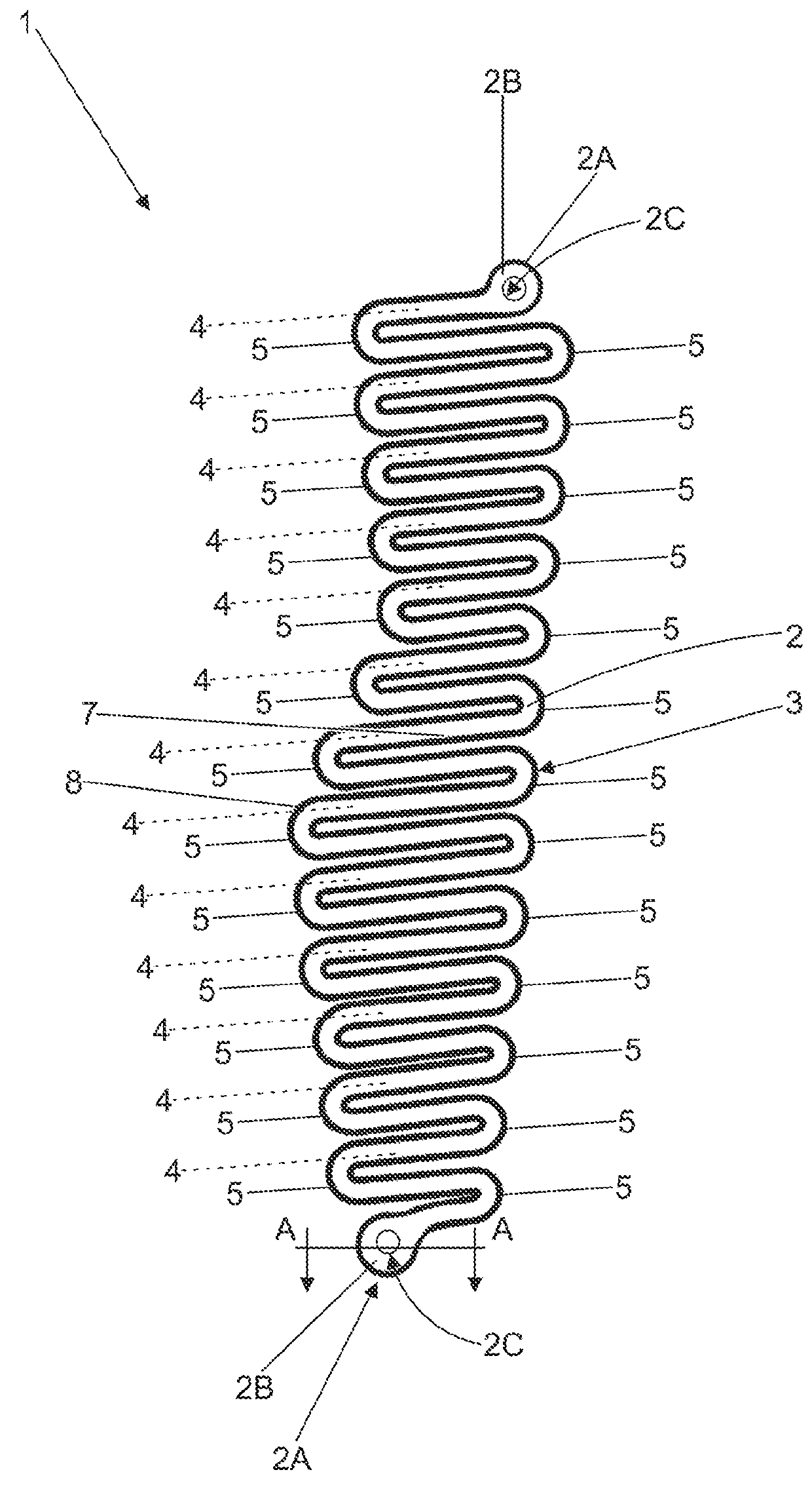
[0026]this invention patent application proposes a stamped resistive element for use in electrical equipment and manufacturing process of stamped resistive element, wherein the stamped resistive element itself is indicated by the numerical reference 1 and consists of a laminar body 2, which is defined as a strip 3 of the flat surface defining parallel portions 4, each of which having continuity with the next through curved portions 5. The two ends 2A of the laminar body 2 have an enlarged surface 2B, which allows the incorporation of a hole 2C that can be crossed by rivets 15 attaching to the electrical connection.

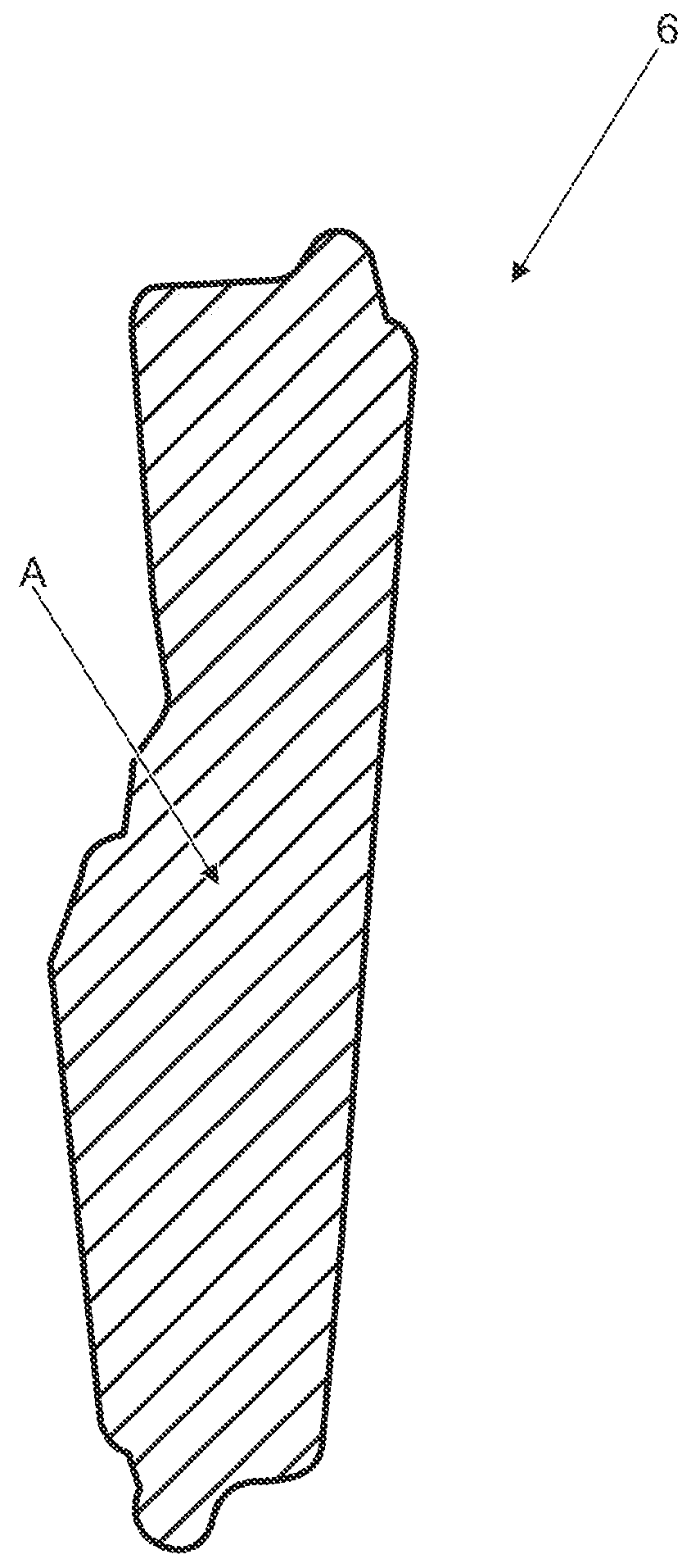
[0027]The laminar body 2 defines a heating and heat transfer area 6, schematically depicted in FIG. 1A and which is established by the cover produced by the parallel 4 and curved 5 portions of the strip 3.

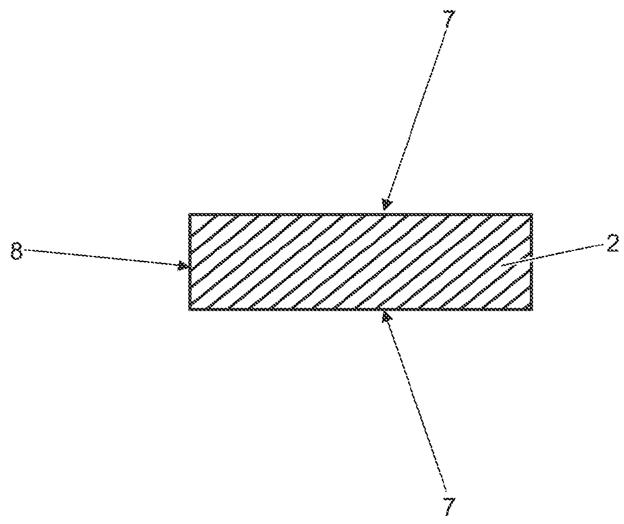
[0028]The stamped resistive element 1 shows two flat faces 7 and a perimeter contour face 8, which are particularly illustrated in FIGS. 1 and 2. The flat faces 7 and the...


PUM


Abstract

A stamped resistive element for use in electrical equipment, manufacturing process of stamped resistive element and apparatus equipped with stamped resistive element are provided. The stamped resistive element is produced from a stamping process and is intended to be used in replacement of conventional helical electrical resistances, whether in hair dryers and similar equipment or in other types of heating equipment. The stamped resistive element is produced as a blank from a metal sheet presenting a known resistive coefficient.

Description

CROSS REFERENCE TO RELATED APPLICATIONS[0001]This application is a continuation of International Application No. PCT / BR2016 / 000086 filed on Feb. 12, 2016, which claims priority of Brazilian application No BR102016003027-7 filed on Feb. 12, 2016 and claims priority of Brazilian application No BR102016006633-6 filed on Mar. 24, 2016, the entire contents of all of which are incorporated by reference herein.BACKGROUND[0002]1. Field of the Invention[0003]This invention patent application proposes a new type of stamped resistive element for use in electrical equipment, which can include hair dryers and other similar equipment, as well as other types of equipment that somehow operate by heating a fluid, whether gaseous or liquid. This invention patent application also addresses the manufacturing process whereby the stamped resistive element is produced.[0004]This invention patent application proposes a new type of resistive element for use in electrical equipment, and can be used in place ...

Claims


Application Information

Patent Timeline
IPC IPC(8): F24H3/04H05B3/10H05B3/02H05B3/00
CPCA45D20/12B26F1/40H05B3/06H05B3/34F24H3/0423H05B2203/035H05B3/10H05B3/026H01C7/00H05B2203/002H05B3/0014B21D53/00B26F2001/4481H01C7/22H05B3/16H05B2203/017H05B2203/022
Inventor IKESAKI, ROBERTO JUN
Owner ACTION TECH IND E COMERCIO DE ELETROELECTRONICSOS LTDA
Why Eureka
Try Eureka