Object Detection Enhancement of Reflection-Based Imaging Unit

a reflection-based imaging and object detection technology, applied in the field of active and passive imaging systems, can solve the problems of insufficient contrast, insufficient illumination, and unclear and indecipherable image conten

Active Publication Date: 2017-09-21
BRIGHTWAY VISION
View PDF7 Cites 83 Cited by
  • Summary
  • Abstract
  • Description
  • Claims
  • Application Information

AI Technical Summary

Problems solved by technology

Vehicle-mounted imaging systems that operate solely using a reflection-based image (active illumination imaging) may sometimes produce unclear and indecipherable image content, such as insufficient contrast between potential objects of interest and the background, or insufficiently lit objects (due to the reflected signal intensity being too low).
As a result, it may be difficult to ascertain with a high degree of confidence the presence of relevant objects in the environment (such as a pedestrian or a vehicle along the road), and to accurately identify whether they pose a potential hazard.
The increased time and processing required to accurately determine potential hazards and relevant objects in the vehicle path based on such reflection-based images also necessitates a longer decision making period for the vehicle operator, which may increase the likelihood of a traffic accident.
Finally, a single camera (or sensor) may be restricted to a particular spectral range, which may limit the object detection capabilities.
Conversely, vehicle-mounted imaging systems that operate solely using passive emission-based imaging provide very limited information, and are only capable of detecting objects in the environment that radiate above a sufficient level (or that are above at least a certain temperature) and that radiate in the selected wavelength range (e.g., infrared).
Accordingly, such passive emission-based imaging systems typically fail to provide a comprehensive image of the entire environment, and can only provide the vehicle operator with limited information relating to relevant objects and potential hazards in the vicinity of the vehicle.
Moreover, it is often difficult for an average person to properly understand and interpret a displayed emission-based image (such as a thermal image).
Even for individuals that have experience and familiarity with these types of images, it usually still takes some time to process and register the connection between the contents of the thermal image and the real-world environment that is represented.
Thus, the increased processing time to identify potential hazards in the thermal image also increases the decision making time of the vehicle operator, which ultimately raises the likelihood of a vehicle accident.

Method used


Image

  • Object Detection Enhancement of Reflection-Based Imaging Unit
  • Object Detection Enhancement of Reflection-Based Imaging Unit
  • Object Detection Enhancement of Reflection-Based Imaging Unit

Examples


Embodiment Construction

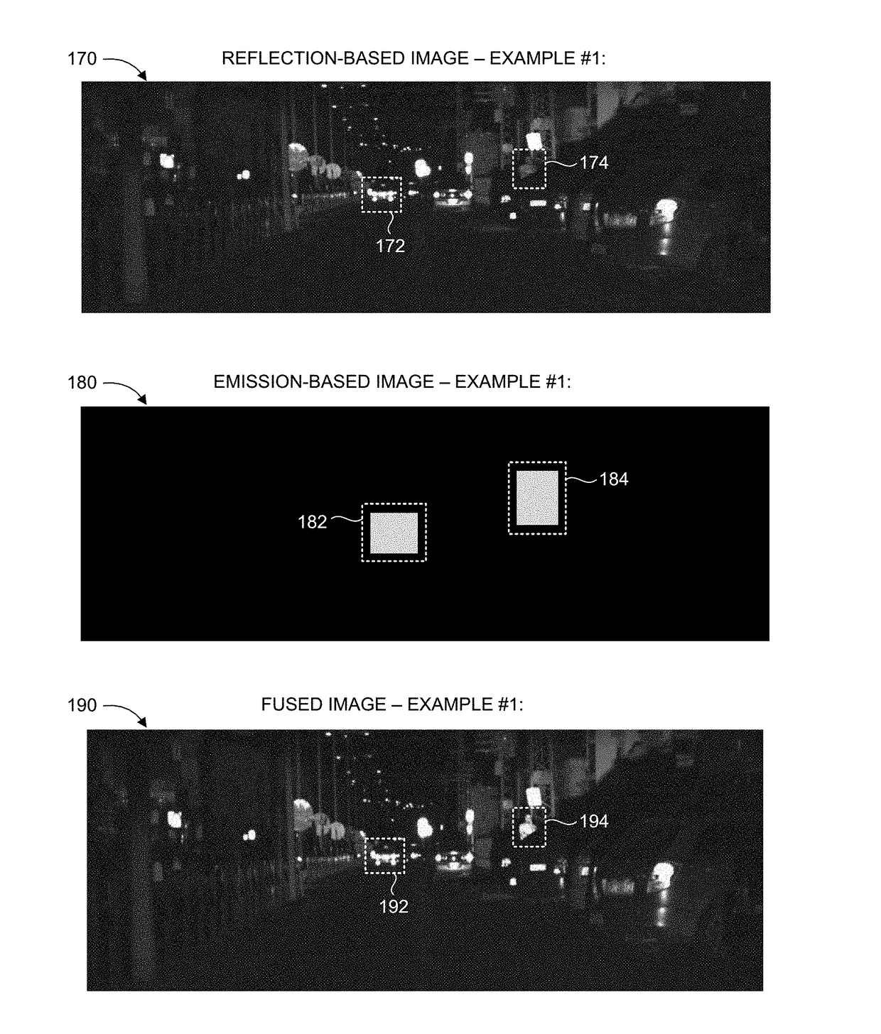
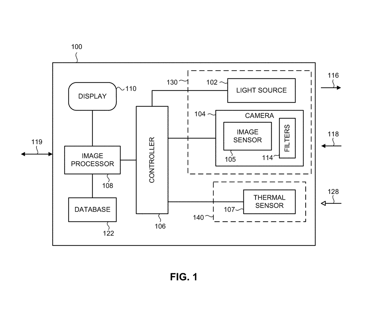
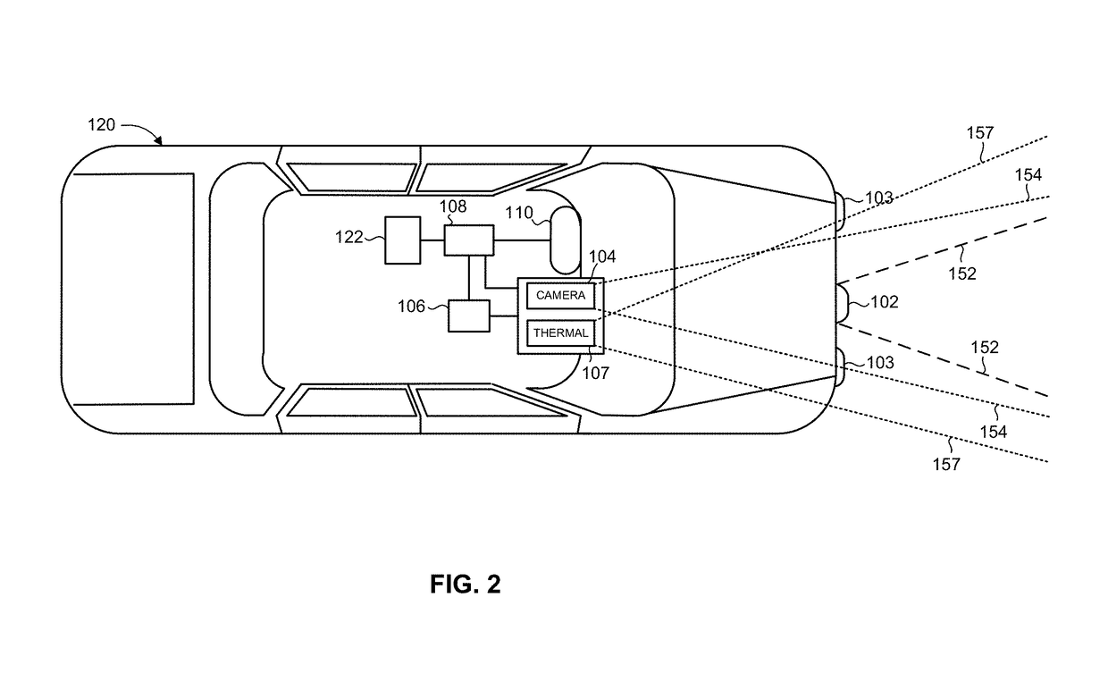
[0020]The present invention overcomes the disadvantages of the prior art by providing an imaging system and method that enhances the object detection capabilities of a reflection-based imaging (e.g., active illumination) detection unit, using an auxiliary detector based on emission-based (e.g., passive) imaging. The imaging system adaptively sets or adjusts a detection characteristic relating to the reflection-based detection unit, such as by selectively modifying at least one imaging parameter or detection threshold, based on information obtained from the emission-based imaging detection unit. The imaging system may further adaptively set or adjust a detection characteristic relating to the emission-based detection unit, based on information obtained from the reflection-based imaging detection unit. A reflection-based image and emission-based image may be combined to form a merged image, which may be processed and / or displayed. Following an initial processing of the images acquired...


PUM


Abstract

Imaging system and method, the system including a main detection unit, an auxiliary detection unit, an image processor, and a controller. The main detection unit includes a light source that emits light pulses and a gated image sensor that receives reflections of the light pulses reflected from a selected depth of field in the environment and converts the reflections into a reflection-based image. The auxiliary detection unit includes a thermal sensor that detects infrared radiation emitted from the environment and generates an emission-based image. The image processor processes and detects at least one region of interest in the acquired reflection-based image and / or acquired emission-based image. The controller adaptively controls at least one detection characteristic of a detection unit based on information obtained from the other detection unit. The image processor detects at least one object of interest in the acquired reflection-based image and / or acquired emission-based image.

Description

CROSS-REFERENCE TO RELATED APPLICATIONS[0001]This application is a National Phase application filed under 35 U.S.C. §371 of PCT International Application No. PCT / IL2015 / 051173 with an International Filing Date of Dec. 3, 2015, which claims priority to Israel Patent Application No. 236114, filed on Dec. 7, 2014, the entire contents of which are incorporated herein by reference.FIELD OF THE INVENTION[0002]The present invention relates to active and passive imaging systems in general, and to imaging systems for object detection in a vehicular environment, in particular.BACKGROUND OF THE INVENTION[0003]Night vision imaging systems produce visible images of an environment having minimal ambient light, which would otherwise not be visible to the human eye. Such systems are used by military and law enforcement units, as well as various civilian applications. One such application is improving the visibility of a vehicle driver during night, rain, fog, or other poor visibility driving condit...

Claims


Application Information

Patent Timeline
Patent Type & Authority Applications(United States)
IPC IPC(8): G06K9/00H04N5/232G01S17/10G01S17/89G01S17/93G06K9/46G06K9/62G01S17/18G01S17/931G06V10/143G06V10/60
CPCG06K9/00805G06K9/4661H04N5/23216G01S17/107G01S17/89G01S17/936G06K9/6293G02B23/12G01S17/18G01S17/931G06V20/56G06V10/143G06V10/60G06V10/811H04N23/57H04N23/11G06F18/256G06V20/58H04N23/62
Inventor GRAUER, YOAV
Owner BRIGHTWAY VISION
Why Eureka
Try Eureka