Multi-band single feed dielectric resonator antenna (DRA) array

a dielectric resonator and antenna array technology, applied in the direction of antennas, simultaneous aerial operations, electrical equipment, etc., can solve the problems of affecting performance, size and cost of the array, and additional complexity

Active Publication Date: 2017-09-21
HUAWEI TECH CO LTD
View PDF3 Cites 51 Cited by
  • Summary
  • Abstract
  • Description
  • Claims
  • Application Information

AI Technical Summary

Problems solved by technology

The use of dual-mode feeds results in additional complexity, size and cost of the array.
Interleaved antennas with a dual mode feed offer lower cost but often suffer from strong coupling between bands which can impact performance.

Method used


Image

  • Multi-band single feed dielectric resonator antenna (DRA) array
  • Multi-band single feed dielectric resonator antenna (DRA) array
  • Multi-band single feed dielectric resonator antenna (DRA) array

Examples


Embodiment Construction

[0018]There is a need for an improved multi-band single feed dielectric resonator antenna (DRA).

[0019]Embodiments are described below, by way of example only, with reference to FIGS. 1-10.

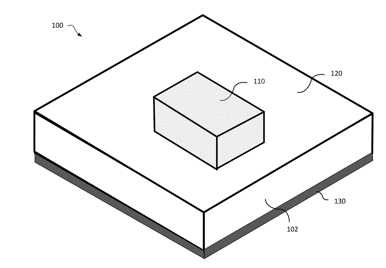
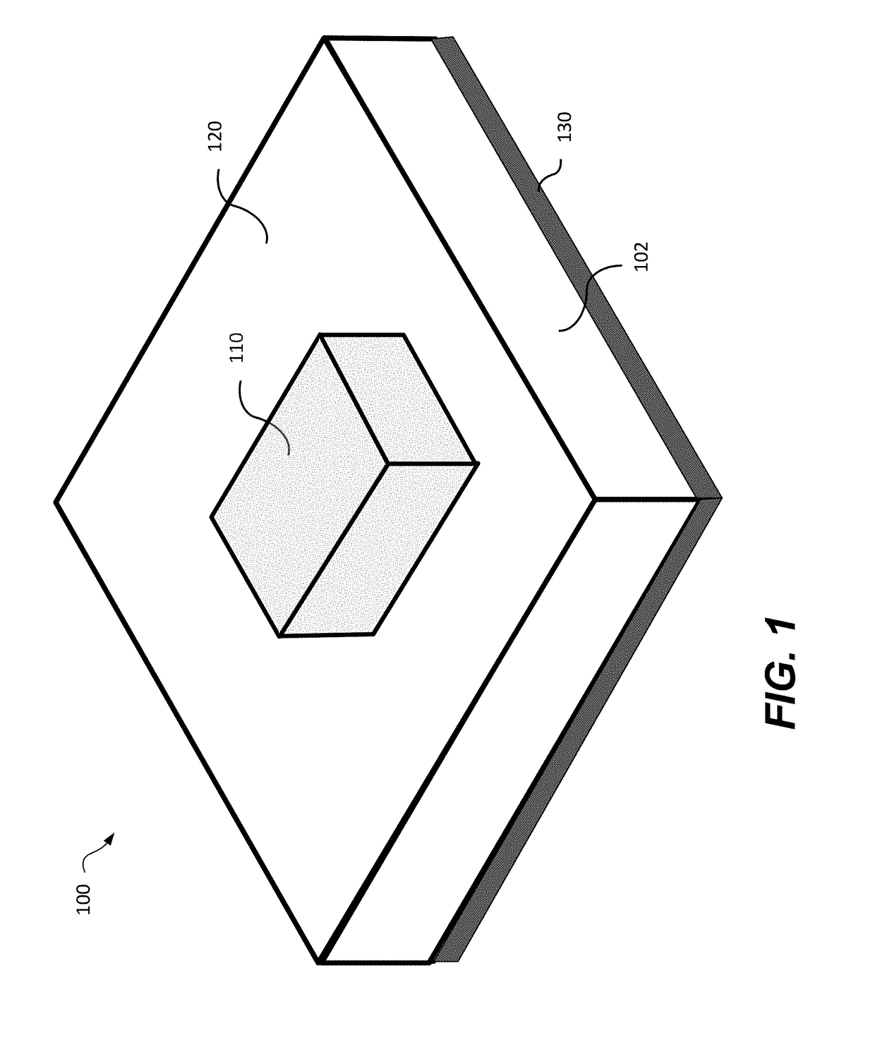
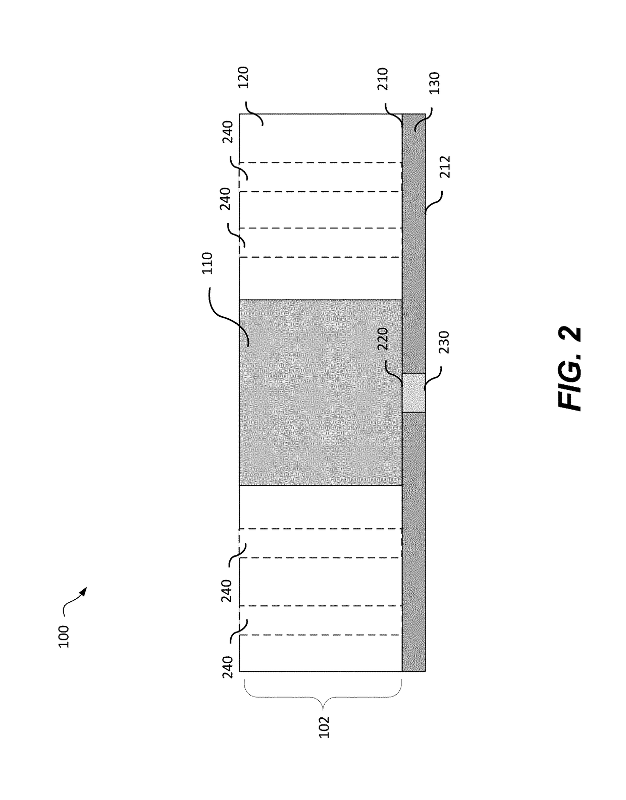
[0020]A multi-band single feed artificial DRA is disclosed. The DRA provides a simplified and efficient design without need for additional feeding layers and diplexer with reduced coupling effects. The DRA is formed from a single monolithic dielectric material providing two regions each having different dielectric constants and therefore a different frequency response. The dielectric constant is determined through physical properties of the dielectric which can be dictated by the doping and composition of the dielectric. Alternatively a different dielectric constant can be achieved by modifying a portion of the dielectric by the introduction of voids, air holes, perforations, or indentation(s) in one region of the antenna dielectric. The physical modification of the dielectric to create a second re...


PUM


Abstract

A multi-band single feed dielectric resonator antenna (DRA) and DRA array are provided. The DRA is made of a dielectric material having a first and second antenna regions wherein the second antenna region has a different dielectric constant than the first antenna region. The dielectric material is supported by a feeding substrate. The feeding substrate has a top surface ground plane having a slot positioned below the first antenna region of the dielectric material and a microstrip feeding line on the bottom surface in alignment with the slot on the top surface ground plane.

Description

TECHNICAL FIELD[0001]The present disclosure relates to multi-band antenna arrays and in particular to multi-band single feed dielectric resonator antennas and antenna arrays.BACKGROUND[0002]A dielectric resonator antenna (DRA) is formed from a dielectric resonator mounted on a metal surface providing a ground plane which is feed a signal for transmission. DRA antennas are used at microwave and higher frequencies, such as millimeter wave, E-Band and fifth generation (5G) spectrum bands due to their size, bandwidth and radiation efficiency. The resonance frequency is determined by the dimensions and dielectric constant εr of the dielectric material which can be determined based upon the composition and structure of the material used.[0003]Multi-band antenna arrays offer increased transmission capacity with small size antennas and steerable multi-band arrays are very beneficial for phased array systems at desired frequency bands. However multi-band interleaved antennas need either isol...

Claims


Application Information

Patent Timeline
Patent Type & Authority Applications(United States)
IPC IPC(8): H01Q9/04H01Q5/50H01Q21/00
CPCH01Q9/0485H01Q5/50H01Q21/0075H01Q21/061
Inventor MIRAFTAB, VAHIDHYJAZIE, FAYEZBOUTAYEB, HALIM
Owner HUAWEI TECH CO LTD
Why Eureka
Try Eureka