
Annuloplasty Implant

a technology of annuloplasty and implant, which is applied in the field of annuloplasty implants, can solve the problems of valve leakage, compromise between the functionality of the implant, incomplete or delayed endothelialization, etc., and achieve the effect of facilitating the delivery of the implant to the target site and minimizing the friction of the implan

Inactive Publication Date: 2017-09-28
MEDTENTIA INT LTD OY
View PDF3 Cites 55 Cited by
  • Summary
  • Abstract
  • Description
  • Claims
  • Application Information

AI Technical Summary

Benefits of technology

The invention provides several technical benefits. Firstly, it enhances safety by reducing the risk of material fatigue and rupture. Secondly, it simplifies the delivery process of the implant by making it easier to reach the target site. Lastly, it minimizes the resistance faced by the implant while moving through the delivery catheter.

Problems solved by technology

The mitral and tricuspid valve leaflets or supporting chordae may degenerate and weaken or the annulus may dilate leading to valve leak.
Annuloplasty rings devised for implantation are over time overgrown and encapsulated by tissue.
Incomplete or delayed endothelialization can be a cause of embolism or thrombosis in a later stage after implantation.
A problem with prior art annuloplasty implants is the compromise between the functionality of the implant during the initial stages, such as during the implantation procedure, and the long term characteristics of the implant, for example with respect to the endothelialization process.
A further problem of prior art devices is the lack of flexibility of the implant in certain situations, which impedes optimal functioning when implanted in the moving heart, or adaptability to varying anatomies.
Material fatigue may nevertheless lead to rupture of the material, that may be unexpected and uncontrolled.
This entails a higher risk to the patient and it is thus a further problem of prior art devices.
The above problems may have dire consequences for the patient and the health care system.
Patient risk is increased.

Method used


Image

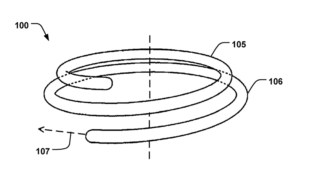
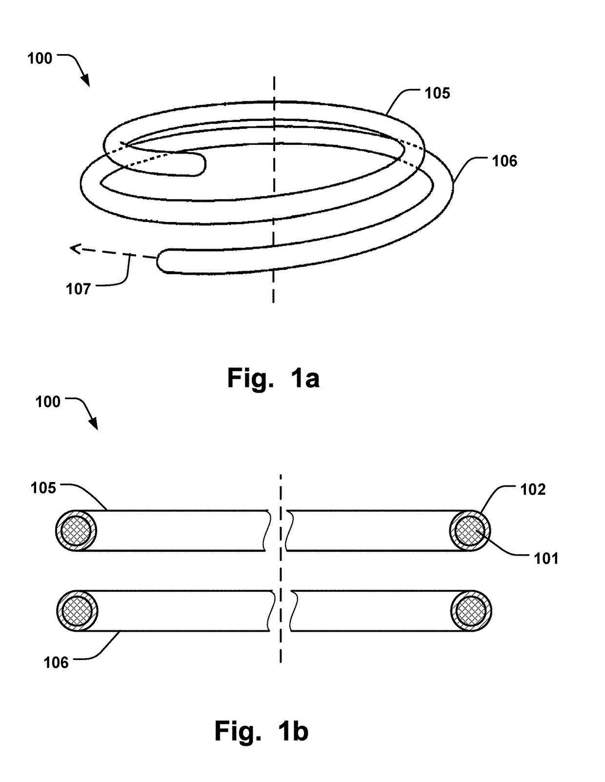
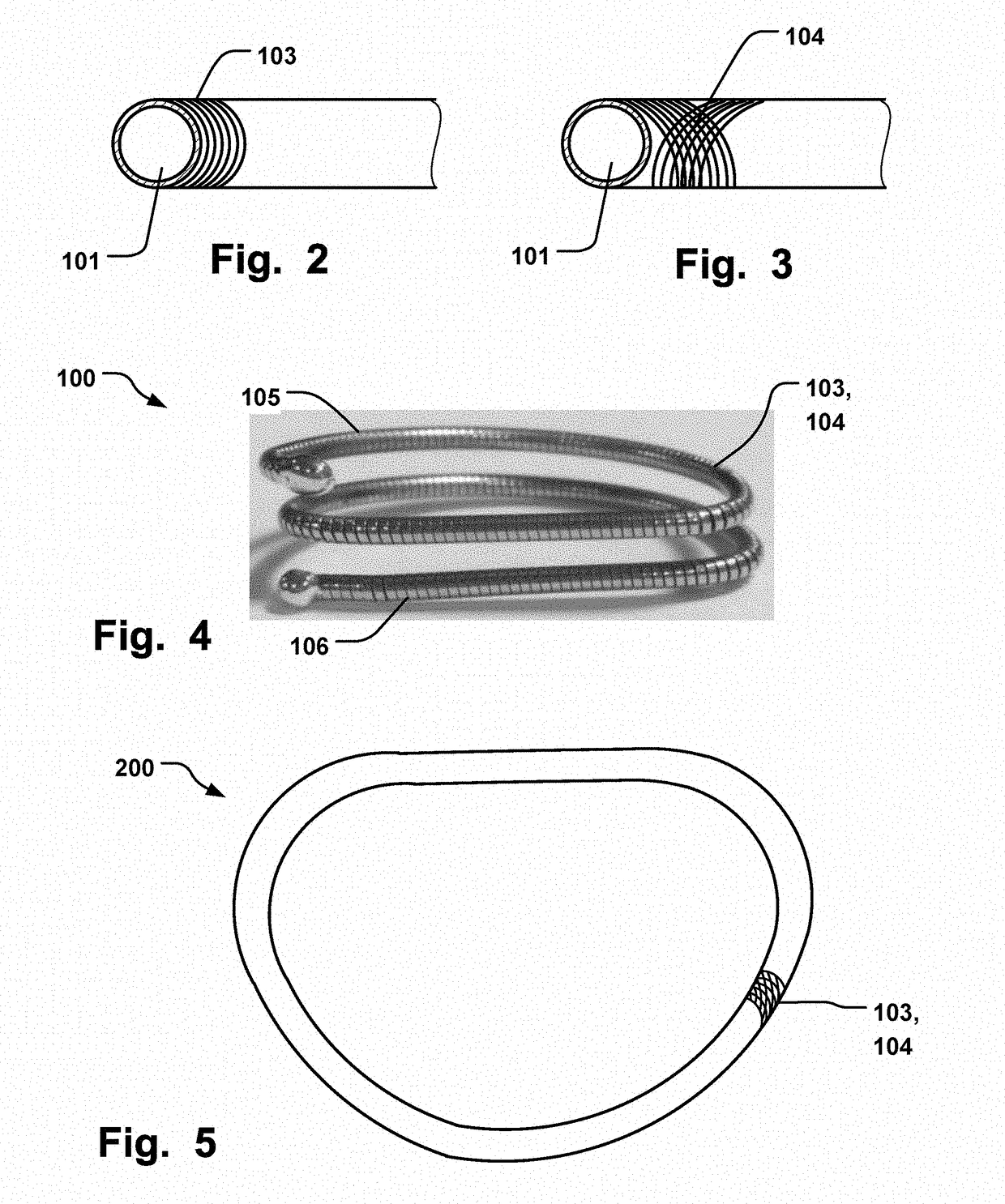
  • Annuloplasty Implant
  • Annuloplasty Implant
  • Annuloplasty Implant

Examples


Embodiment Construction

[0032]Specific embodiments of the invention will now be described with reference to the accompanying drawings. This invention may, however, be embodied in many different forms and should not be construed as limited to the embodiments set forth herein; rather, these embodiments are provided so that this disclosure will be thorough and complete, and will fully convey the scope of the invention to those skilled in the art. The terminology used in the detailed description of the embodiments illustrated in the accompanying drawings is not intended to be limiting of the invention. In the drawings, like numbers refer to like elements.

[0033]The following description focuses on an embodiment of the present invention applicable to cardiac valve implants such as annuloplasty rings. However, it will be appreciated that the invention is not limited to this application but may be applied to many other annuloplasty implants and cardiac valve implants including for example replacement valves, and o...


PUM


Abstract

An annuloplasty implant comprising an inner core of a shape memory material, an outer covering arranged radially outside said inner core material to cover at least part of said inner core, wherein said outer covering is resilient to conform to said inner core during movement of said shape memory material, wherein said outer covering comprises a material having surface properties to promote endothelialization. Two portions of the implant may be joined by a recess to be flexible with respect to each other by a bending motion at the recess. The two portions may also have a predefined breaking point at the recess.

Description

FIELD OF THE INVENTION[0001]This invention pertains in general to the field of cardiac valve replacement and repair. More particularly the invention relates to an annuloplasty implant, such as an annuloplasty ring or helix, for positioning at the heart valve annulus.BACKGROUND OF THE INVENTION[0002]Diseased mitral and tricuspid valves frequently need replacement or repair. The mitral and tricuspid valve leaflets or supporting chordae may degenerate and weaken or the annulus may dilate leading to valve leak. Mitral and tricuspid valve replacement and repair are frequently performed with aid of an annuloplasty ring, used to reduce the diameter of the annulus, or modify the geometry of the annulus in any other way, or aid as a generally supporting structure during the valve replacement or repair procedure.[0003]Annuloplasty rings devised for implantation are over time overgrown and encapsulated by tissue. The process of endothelialization, leading to the encapsulation of the implant by...

Claims


Application Information

Patent Timeline
Patent Type & Authority Applications(United States)
IPC IPC(8): A61F2/24
CPCA61F2/2445A61F2250/0029A61F2230/0091A61F2/2454A61F2/2448A61F2250/0036A61F2250/0071
Inventor O'CARROLL, GERPUGH, MARKMORAN, ADRIANZERKOWSKI, HANS-REINHARDKERANEN, OLLI
Owner MEDTENTIA INT LTD OY
Learn More