Iud insertion devices, and related methods and kits therefor

a technology of insertion devices and iuds, which is applied in the field of intrauterine systems (ius), intrauterine devices (iuds), insertion devices, and can solve problems such as pain and even loss of consciousness for patients, negative affecting the mobility of sperm, and difficult for an embryo to plant in the wall

Inactive Publication Date: 2017-09-28
MEDICINES360
View PDF0 Cites 5 Cited by
  • Summary
  • Abstract
  • Description
  • Claims
  • Application Information

AI Technical Summary

Benefits of technology

[0039]Disclosed are two-handed IUD insertion devices. The two-handed IUD insertion devices comprise: an elongated sheath having a proximal end and a distal end and a lumen extending between the proximal end and the distal end; a plunger having a proximal end and a distal end with a plurality of notches along its length wherein the plunger is configured to move axially within the lumen of the elongated sheath; a grip secured to the proximal end of the elongated sheath wherein the grip has an interior surface and an exterior surface and a centrally translating member configured to move without rotation towards a central axis to engage one of the plurality of notches on the plunger and an external button that engages the centrally translating member to disengage the centrally translating member away from an engaged notch; a proximally positioned tab handle secured to the proximal end of the plunger. In some configurations, the tab handle has a hinge and / or a textured surface. A flange can be positioned about an exterior of the elongated sheath and visible markings can be provided on the sheath. The two-handed IUD insertion device operates in combination with an intrauterine device (IUD). An elongate member of the IUD comprises a core part containing a polymeric reservoir with an active agent around which a rate limiting polymer membrane has been fitted. The active agent in the reservoir can be a hormone used for the treatment of menopausal troubles or for contraception.

Problems solved by technology

Copper IUDs work by negatively affecting the mobility of sperm and preventing the sperm from joining an egg.
Additionally, the copper body positioned within the uterus irritates the lining of the uterus and uterine wall making it difficult for an embryo to plant in the wall if the egg is fertilized by the sperm.
Conventional insertion devices used with IUDs (which includes devices used for IUSs) can cause pain and even loss of consciousness to a patient during the insertion procedure as a result of induction of a vagal reflex response.
Conventional insertion devices lack smooth operability and exhibit issues with ease of use.

Method used


Image

  • Iud insertion devices, and related methods and kits therefor
  • Iud insertion devices, and related methods and kits therefor
  • Iud insertion devices, and related methods and kits therefor

Examples


Embodiment Construction

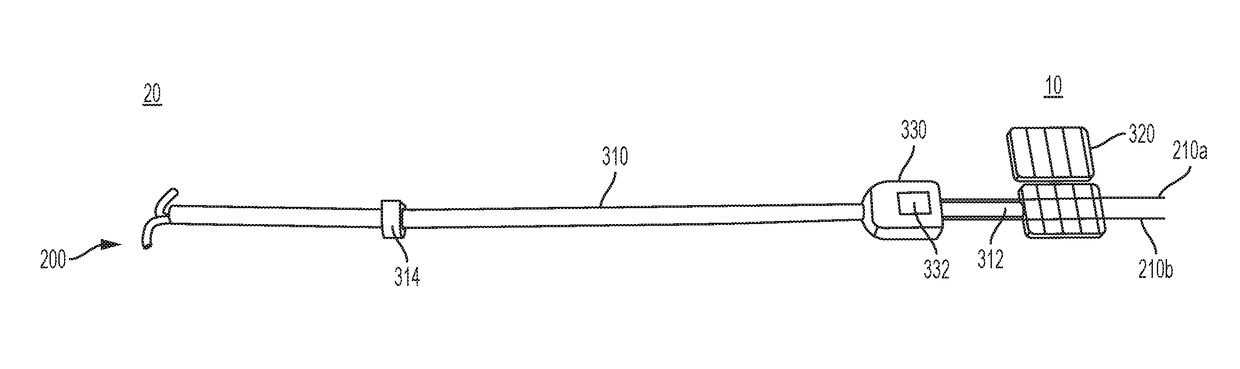
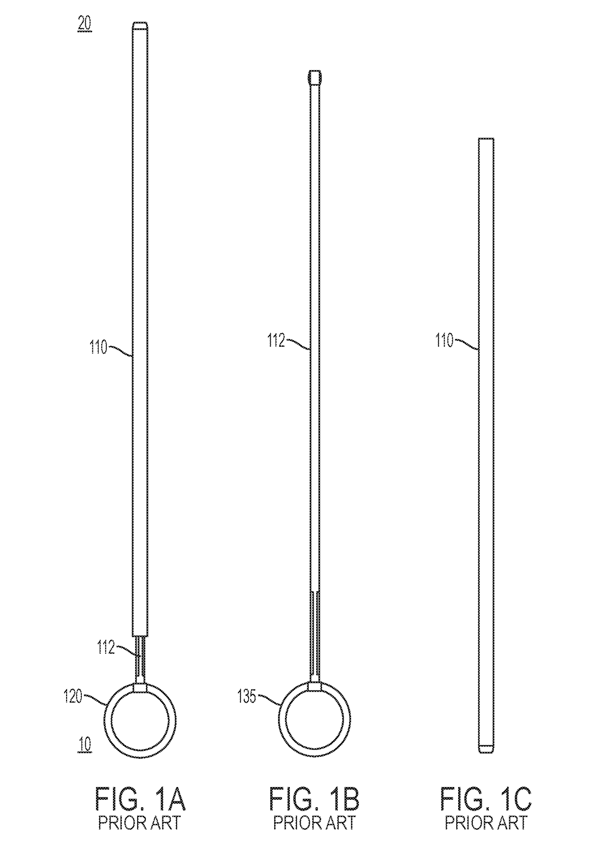
[0064]Conventional intrauterine insertion devices include an inserter or insertion device 100 such as the device shown in FIGS. 1A-1C, which includes a sheath 110 or insertion tube having a proximal end 10 and a distal end 20 and a lumen extending between the proximal end and the distal end of the sheath 110 for housing the IUD (shown in FIG. 2), a plunger 112 for pushing the IUD through the sheath 110, and a user interface such as a handle 120 for holding the insertion device. The device shown in FIGS. 1A-1C requires a two-handed operation, whereby the operator or user holds the handle 120 in one hand and the sheath 110 in another hand.

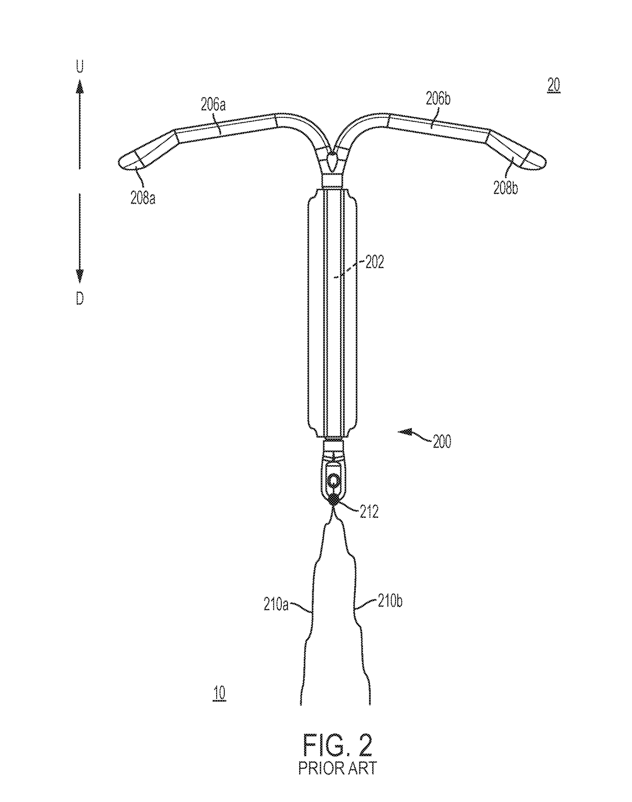
[0065]The disclosed insertion devices can, for example, be used with a T-shaped IUD 200, such as the IUD as shown in FIG. 2. IUDs typically have a length of from about 31.90 mm to about 32.22 mm and a width of from about 31.81 mm to about 32.13 mm when the IUD is in the fully deployed position. As will be appreciated by those skilled in the art, the ...


PUM


Abstract

Disclosed are two-handed IUD insertion devices for positioning an intrauterine device (IUD) in the uterus which includes a plunger, a sheath, a grip and a handle where the axial movement of the plunger is controlled via features along the length of the plunger in communication with a grip feature.

Description

CROSS-REFERENCE[0001]This application claims the benefit of U.S. Provisional Application No. 62 / 312,828, filed Mar. 24, 2016, entitled IUD Insertion Devices, and Related Methods and Kits Therefor, which application is incorporated herein by reference.BACKGROUND[0002]Field of the Invention[0003]The disclosure relates to intrauterine systems (IUS), intrauterine devices (IUDs), insertion devices, methods of use, and kits therefor.[0004]Background of the Invention[0005]An intrauterine device (IUD) is an object that, when placed in the uterus of a female, acts as a birth control device to prevent pregnancy. Two types of IUDs are commonly available, copper-containing devices and hormone-containing devices that release a progestogen. Hormone containing devices are considered to be a different form of birth control and may be distinguished in the literature by the term intrauterine system (IUS).[0006]Copper IUDs work by negatively affecting the mobility of sperm and preventing the sperm fro...

Claims


Application Information

Patent Timeline
Patent Type & Authority Applications(United States)
IPC IPC(8): A61F6/18A61M31/00A61F6/14
CPCA61F6/18A61M31/00A61F6/144
Inventor DECKMAN, ROBCARSON, CRAIGGUYER, CURTNETT, DAVIDCREININ, MITCHELL
Owner MEDICINES360
Why Eureka
Try Eureka