Intraurinary systems, iud insertion devices, and related methods and kits therefor

a technology of intrauterine devices and intrauterine tubes, which is applied in the field of intrauterine systems, intrauterine devices (iuds), insertion devices, and related methods and kits therefor, can solve the problems of pain and even loss of consciousness for patients, affecting the mobility of sperm, and difficult for an embryo to plant in the wall

Active Publication Date: 2013-01-17
MEDICINES360
View PDF4 Cites 38 Cited by
  • Summary
  • Abstract
  • Description
  • Claims
  • Application Information

AI Technical Summary

Benefits of technology

[0011]An aspect of the disclosure is directed to insertion devices comprising: an elongated sheath having a proximal end and a distal end and a lumen extending between the proximal end and the distal end; an elongated inner member having a proximal end and a distal end disposable within the lumen of the elongated sheath; a proximally positioned user interface, wherein the proximally positioned user interface further comprises one or more elongated guides formed at least partially therein and along at least a portion of a length thereof; and a moveable sheath slider in communication with the elongated sheath wherein the moveable sheath slider is adaptable and configurable to securely move within the elongated guide and further wherein the moveable sheath slider controls axial movement of the elongated sheath. The elongated guide is further configurable to comprise one or more motion control features along the length of the elongated guide. Additionally, the one or more motion control features are selected from the group comprising a hard motion control feature, a soft motion control feature. Moreover, the one or more motion control features comprises at least one force-limiting feature configurable to limit an amount of force applied to the moveable sheath slider. The one or more motion control features are selectable from the group comprising detents, notches, grooves, protrusions, tabs, ridges, flanges, flaps, gates, flexible members, elongated guide contours, and elongated guide curved surface. Additionally, the elongated guide has a length, a width and a depth, and further wherein the elongated guide width is at least one of a variable length along and a staged width selected from two or more of a first width and a second width. The elongated guide can further be configured to have an in-plane profile selected from rectangular, s-shaped, c-shaped, u-shaped, w-shaped, circular, semi-circular, and oval. The sheath slider can also be configured to comprise one or more surface profiles adapted and configured to mechanically complement the one or more motion control features. The one or more surface profiles of the sheath slider are selected from the group comprising one or more of each of non-planar surfaces, curved surfaces, and angled surfaces. Additionally, the housing and the sheath slider further comprises one or more alignment surfaces, wherein the one or more alignment surfaces of the housing is adapted and configured to mechanically complement the one or more alignment surfaces of the sheath. In at least some configurations, a first sheath slider alignment surface aligns with a first housing alignment surface at a first position along the length of the elongated guide. Additionally, the one or more sheath slider alignment surfaces and the one or more housing alignment surfaces are selected from the group comprising a curved surface, an angled surface, a tilted surface and a dimensional surface. The elongated guide can further be configured to comprise one or more cavities on one or more of the proximal end of the elongated guide and the distal end of the elongated guide wherein the one or more cavities are adapted and configured to house at least a portion of the movable sheath slider. In at least some configurations, the devices further comprise a string control slider. The string control slider can be adaptable and configurable to securely move within the elongated guide. Additionally, the elongated sheath slider and the string control slider are adapted and configured to operate at least one of simultaneously and independently within one or more elongated guides. In at least some configurations, the sheath slider and the string control slider are telescopically movable along at least a first portion of the elongated guide, and further wherein the sheath slider and the string control slider are configurable such that at least one of the sheath slider and the string slider partially surrounds the remaining slider. The sheath slider and string control slider are further configurable to comprise one or more vertical surfaces, wherein the one or more vertical surfaces are selected from the group comprising a first sheath slider vertical surface, a second sheath slider vertical surface, a first string control slider vertical surface, and a second string control vertical surface, wherein one or more of the vertical surfaces are configured to form an aligned adjacent surface at one or more positions along the length of the elongated guide. Typically, devices are configurable such that the sheath slider and the string control slider have a combined width less than or equal to at least one of 0.75 inches (19 mm), 0.7 inches (17.8 mm), 0.5 inches (12.7 mm), 0.35 inches (8.9 mm), or 0.25 inches (6.3 mm). The insertion device is also configurable to receive an IUD within the distal end of the lumen of the elongated sheath further comprising at least one string locking feature adaptable and configurable to secure one or more string components of the IUD. In some configurations the at least one string locking feature comprises one or more of a cleft, a clamp, a wedge, a pincher, a spring, or teeth. In other configurations, the string locking feature comprises a cleft, and the string unlocking feature comprises a movable member which pushes the one or more strings out of the cleft to unlock the one or more strings. The distal end of the elongated sheath is also configurable such that it has an atraumatic tip selected from the group comprising a rounded tip and a tapered tip. The distal end of the elongated sheath has an outer diameter of about 3 mm to 5 mm. In some configurations, the distal end of the elongated sheath has an outer diameter which is equal to or less than 80%, 50%, 30% of the outer diameter of the proximal end of the elongated sheath. Additionally, the distal end of the elongated sheath is configurable such that it has an outer diameter which is less than the maximum cross-sectional dimension of an IUD positionable within the lumen of the elongated sheath. In at least some configurations, the distal end of the elongated sheath further comprises one or more slits or flaps at the forward end of the sheath. Additionally, one or more feedback mechanisms can be provided which selected from the group comprising audible, visible, and tactile.

Problems solved by technology

Copper IUDs work by negatively affecting the mobility of sperm and preventing the sperm from joining an egg.
Additionally, the foreign copper body positioned within the uterus also irritates the lining of the uterus and uterine wall making it difficult for an embryo to plant in the wall if the egg is fertilized by the sperm.
Conventional insertion devices used with IUDs (which includes devices used for IUSs) can cause pain and even loss of consciousness to a patient during the insertion procedure as a result of induction of a vagal reflex response.
Conventional insertion devices lack smooth operability and exhibit issues with ease of use.

Method used


Image

  • Intraurinary systems, iud insertion devices, and related methods and kits therefor
  • Intraurinary systems, iud insertion devices, and related methods and kits therefor
  • Intraurinary systems, iud insertion devices, and related methods and kits therefor

Examples


Embodiment Construction

I. Insertion Procedure

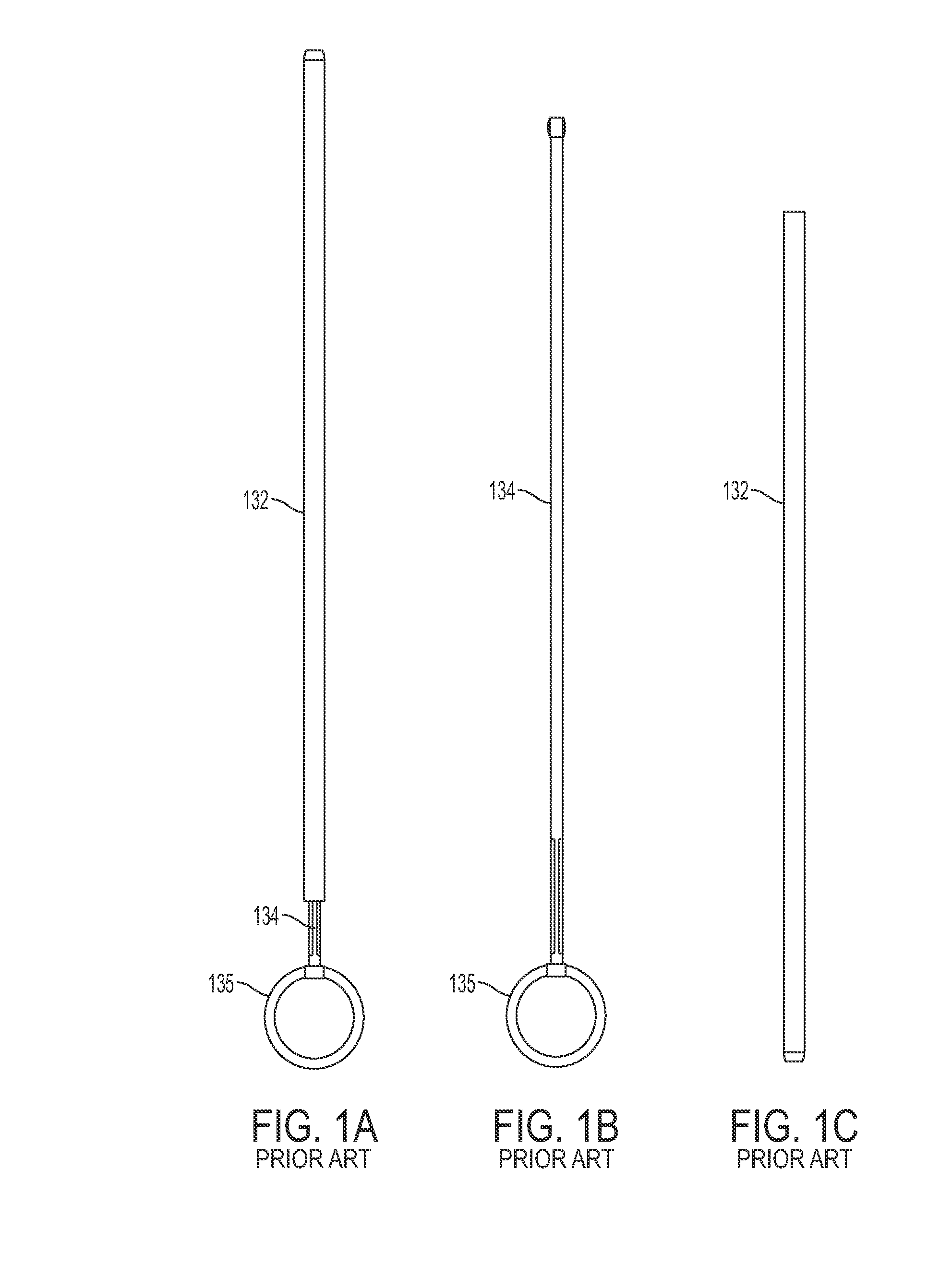
[0054]Conventional intrauterine insertion devices include an inserter or insertion device such as the device shown in FIGS. 1A-1C, which includes a sheath 132 having a proximal end and a distal end and a lumen extending between the proximal end and the distal end for housing the IUD, a plunger 134 for pushing the IUD through the sheath, and user interface such as a handle 135 for holding the insertion device. The device shown in FIGS. 1A-1C requires a two-handed procedure, whereby the operator holds the handle 135 in one hand and the sheath 132 in another hand.

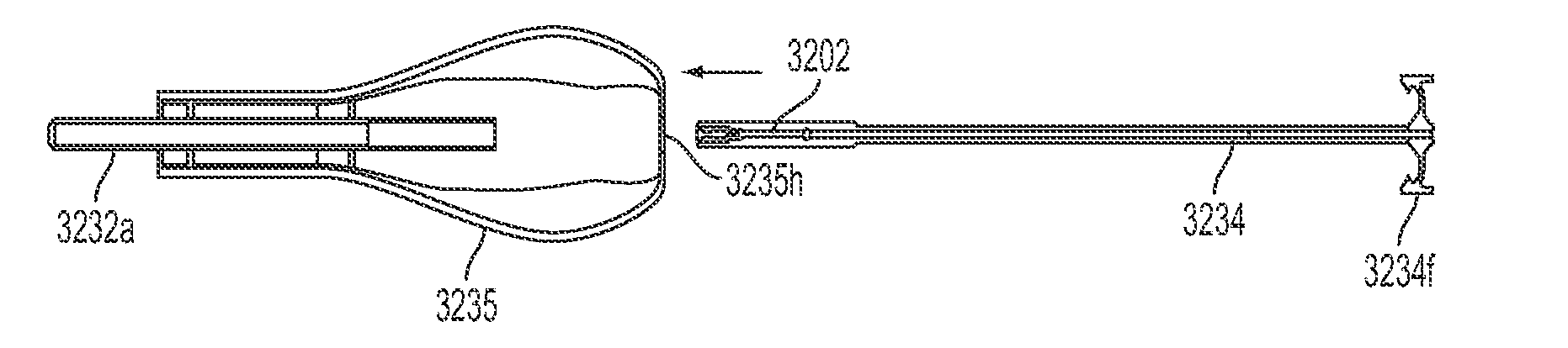
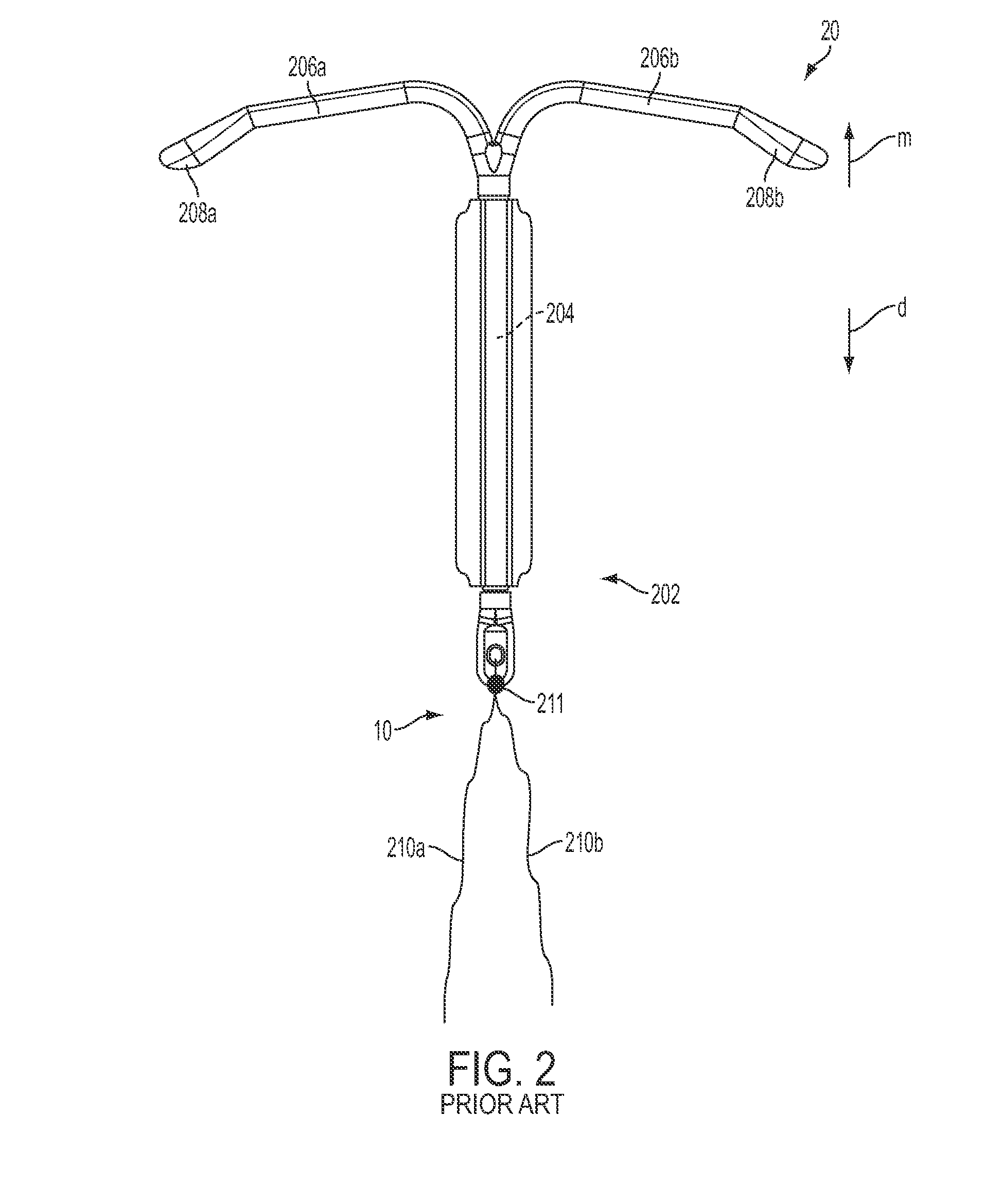
[0055]As will be discussed in more detail below, in contrast to conventional insertion devices, such as depicted in FIG. 1, the insertion devices of the present disclosure are configured to house an IUD during the insertion procedure and is further configured to aid in positioning the IUD during the insertion procedure as well as advancing the IUD from the insertion device into a patient's uterus. The ins...


PUM


Abstract

The present disclosure is related to an intrauterine system (insertion device) including an intrauterine device (IUD), an insertion device or applicator for inserting the IUD into the cervix of a female patient, methods related to the insertion procedure, and methods of manufacture for the insertion device.

Description

CROSS-REFERENCE[0001]This application claims the benefit of U.S. Provisional Application No. 61 / 506,434, filed Jul. 11, 2011, which application is incorporated herein by reference.BACKGROUND OF THE INVENTION[0002]1. Field of the Invention[0003]The disclosure relates to intraurinary systems, intrauterine devices (IUDs), insertion devices, methods of use, and kits therefor.[0004]2. Background of the Invention[0005]An intrauterine device (IUD) is an object that, when placed in the uterus of a female, acts as a birth control device to prevent pregnancy. Two types of IUDs are commonly available, copper-containing devices and hormone-containing devices that release a progestogen. Hormonal containing devices are considered to be a different form of birth control and are may be distinguished in the literature by the term intrauterine system (IUS).[0006]Copper IUDs work by negatively affecting the mobility of sperm and preventing the sperm from joining an egg. Additionally, the foreign coppe...

Claims


Application Information

Patent Timeline
Patent Type & Authority Applications(United States)
IPC IPC(8): A61F6/18
CPCA61F6/18A61F6/144A61F6/12
Inventor DECKMAN, ROBREPP, RICHARD E.GUYER, CURTWESTENDORF, JUSTINPARMER, TIMOTHY
Owner MEDICINES360
Why Eureka
Try Eureka