Stabilizing system for deep drilling

a stabilizing system and deep drilling technology, applied in drilling rods, drilling accessories, earthwork drilling and mining, etc., can solve problems such as severe drag, blockage of the movement of the drill string, and problems such as balling can create problems

Active Publication Date: 2017-09-28
ADNOC
View PDF2 Cites 2 Cited by
  • Summary
  • Abstract
  • Description
  • Claims
  • Application Information

AI Technical Summary

Benefits of technology

[0030]The method comprises the steps of (a) applying a positive force onto the stabilizing system in longitudinal direction, i.e. in drilling direction, causing the column to move to the drilling position and causing the overall longitudinal length of the stabilizing system to shorten such that the at least one spacer is moved to the expanded position. In other words, by performing this step the stabilizing function of the stabilizing system is activated as the spacer is moving to the expanded position.

Problems solved by technology

This balling can create problems, in particular during pulling-out-of-hole (POOH) and / or running-in-hole (RIH) operations.
For example, as illustrated in FIG. 3, when trying to retrieve the drill string out of the hole (POOH), problems arise: The accumulated mud cake 7 can cause a severe drag, and even jam the movement of the drill string.
Accordingly, POOH operations can take much longer due to balling, or in the worst case, the drill string cannot be removed from the hole at all and has to be cut off.
However, these techniques are either expensive in cost, suited for one-time use only, or are ineffective in solving the issue.

Method used


Image

  • Stabilizing system for deep drilling
  • Stabilizing system for deep drilling
  • Stabilizing system for deep drilling

Examples


Embodiment Construction

[0033]In the following the invention is described exemplarily with reference to the enclosed figures:

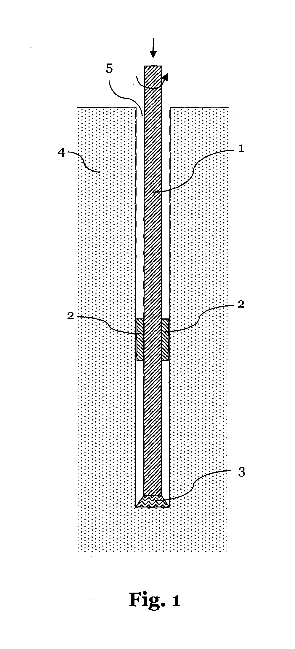
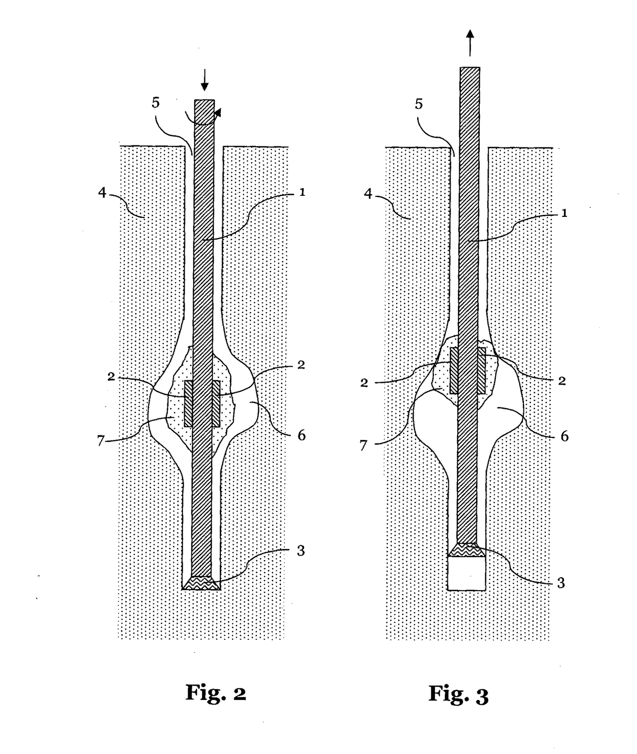
[0034]FIGS. 1-3 illustrate schematically a drilling system in different configurations.

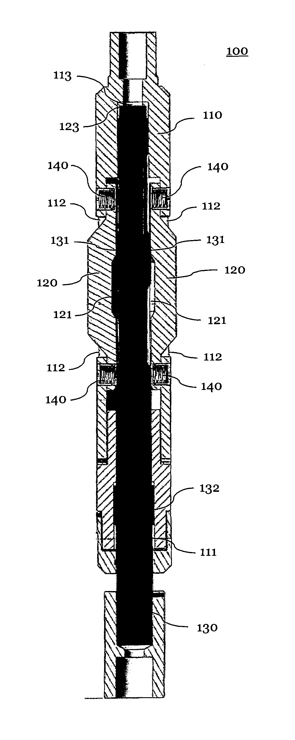
[0035]FIG. 4 illustrates a preferred embodiment of a stabilizing system according to the present invention.

[0036]FIG. 5 is a cross-sectional view of the stabilizing system of FIG. 3.

[0037]FIG. 6 illustrates the stabilizing system of FIG. 4 in another configuration.

[0038]FIG. 7 is a cross-section view of the stabilizing system of FIG. 6.

[0039]FIG. 8 illustrates a cross-section of another stabilizing system according to a preferred embodiment of the present invention.

[0040]FIG. 9 illustrates another preferred embodiment of a stabilizing system according to the present invention.

[0041]FIGS. 10 and 11 illustrate two respective cross-sections of the stabilizing system of FIG. 9.

[0042]FIG. 4 illustrates a stabilizing system 100 according to the present invention, which is adapted to be connected to drill...


PUM


Abstract

The present invention relates to a stabilizing system (100, 200, 300) adapted to be used in a drilling system, wherein the transversal diameter of the stabilizing system (100, 200, 300) increases when drilling forces are applied onto the stabilizing system (100, 200, 300). The invention further comprises a corresponding method for drilling a hole.

Description

1. FIELD OF THE INVENTION[0001]The present invention relates to a deep drilling system and in particular to a stabilizing system having expandable blades and is adapted to be used in the deep drilling system.2. TECHNICAL BACKGROUND[0002]In a deep drilling system, a drill bit is typically connected via several drill pipes, forming a drill string, to a drilling motor. Such a setup is also generally illustrated in FIG. 1. The drilling motor, provided on the earth's surface, applies drilling forces—the longitudinal and rotational forces as illustrated by arrows in FIG. 1—onto the drill string 1 such that the drill bit 3 advances further into the ground 4, thereby creating a bore hole 5. Since bore holes can reach depths of up to several kilometers, it is desired that the drill string 1 is centered in the bore hole. Particularly, the sections close to the drill bit are centered such that the drill bit 3 advances in a defined direction into the ground. For these reasons, stabilizers are t...

Claims


Application Information

Patent Timeline
Patent Type & Authority Applications(United States)
IPC IPC(8): E21B17/10
CPCE21B17/1078E21B17/1021E21B17/1014E21B17/10
Inventor AL AMERI, FAHED SALEM SALEH AWADHAL AWADHI, FARHAAD KHALED SAEED MOHAMED
Owner ADNOC
Why Eureka
Try Eureka