
Pattern forming method, semiconductor device manufacturing method and phase shift photomask having dummy gate patterns

a technology of semiconductor devices and gate patterns, which is applied in the direction of photomechanical instruments, photomechanical equipment, originals for photomechanical treatment, etc., can solve the problems of light distortion and affect the gate pattern, and achieve the effect of reducing the length of each gate pattern remarkably

Active Publication Date: 2006-09-21
RENESAS ELECTRONICS CORP
View PDF3 Cites 3 Cited by
  • Summary
  • Abstract
  • Description
  • Claims
  • Application Information

AI Technical Summary

Benefits of technology

[0011] Also, according to the optical proximity effect caused by the light interference, since the gate patterns are arranged in parallel with each other, the longitudinal length of each of the gate patterns is remarkably decreased and the corners of the gate patterns are remarkably rounded.

Problems solved by technology

In the above-described second prior art manufacturing method, however, since positive use is made of the optical interference, the gate patterns are affected by the distortion of light, i.e., the aberration of a projection lens.

Method used


Image

  • Pattern forming method, semiconductor device manufacturing method and phase shift photomask having dummy gate patterns
  • Pattern forming method, semiconductor device manufacturing method and phase shift photomask having dummy gate patterns
  • Pattern forming method, semiconductor device manufacturing method and phase shift photomask having dummy gate patterns

Examples


Embodiment Construction

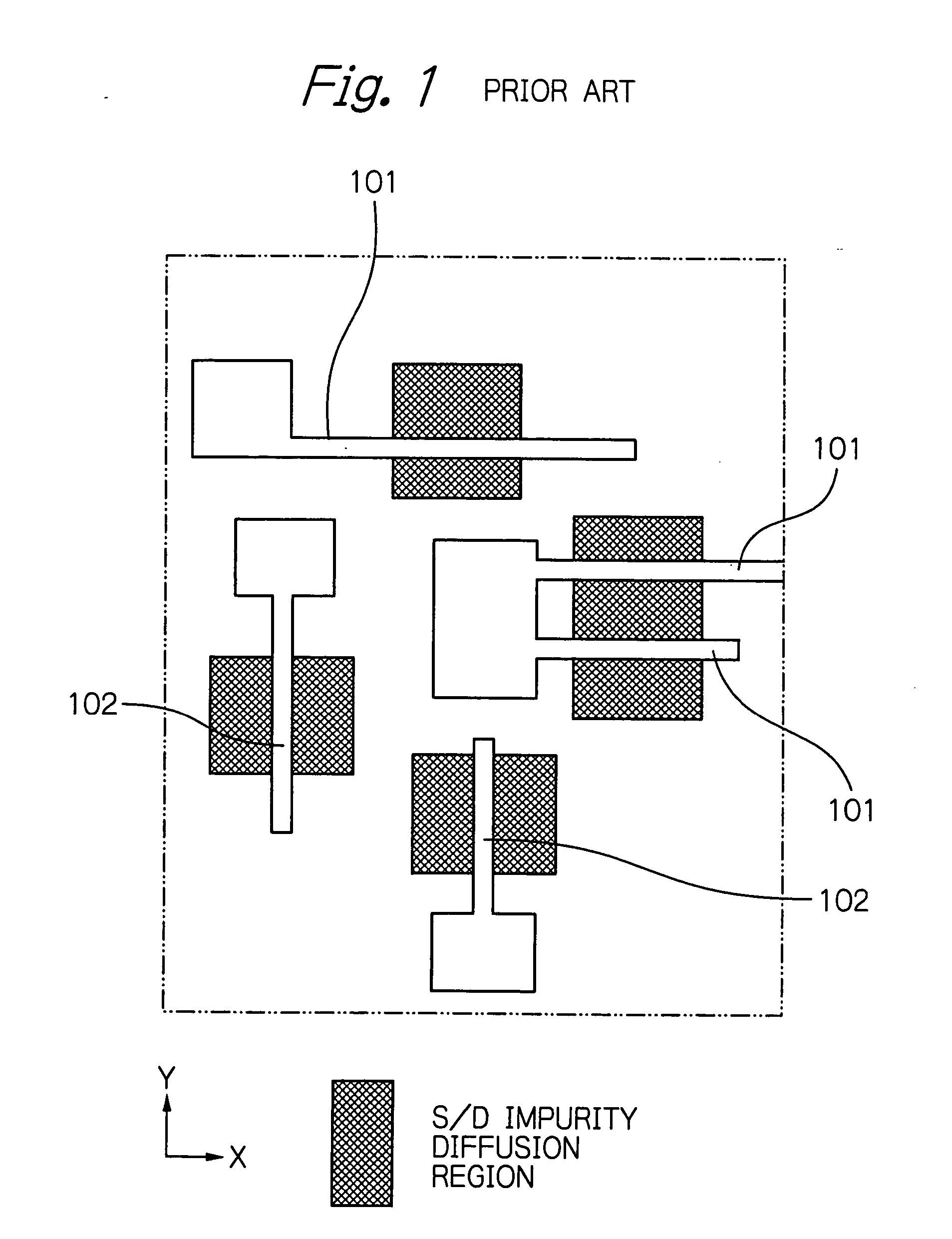
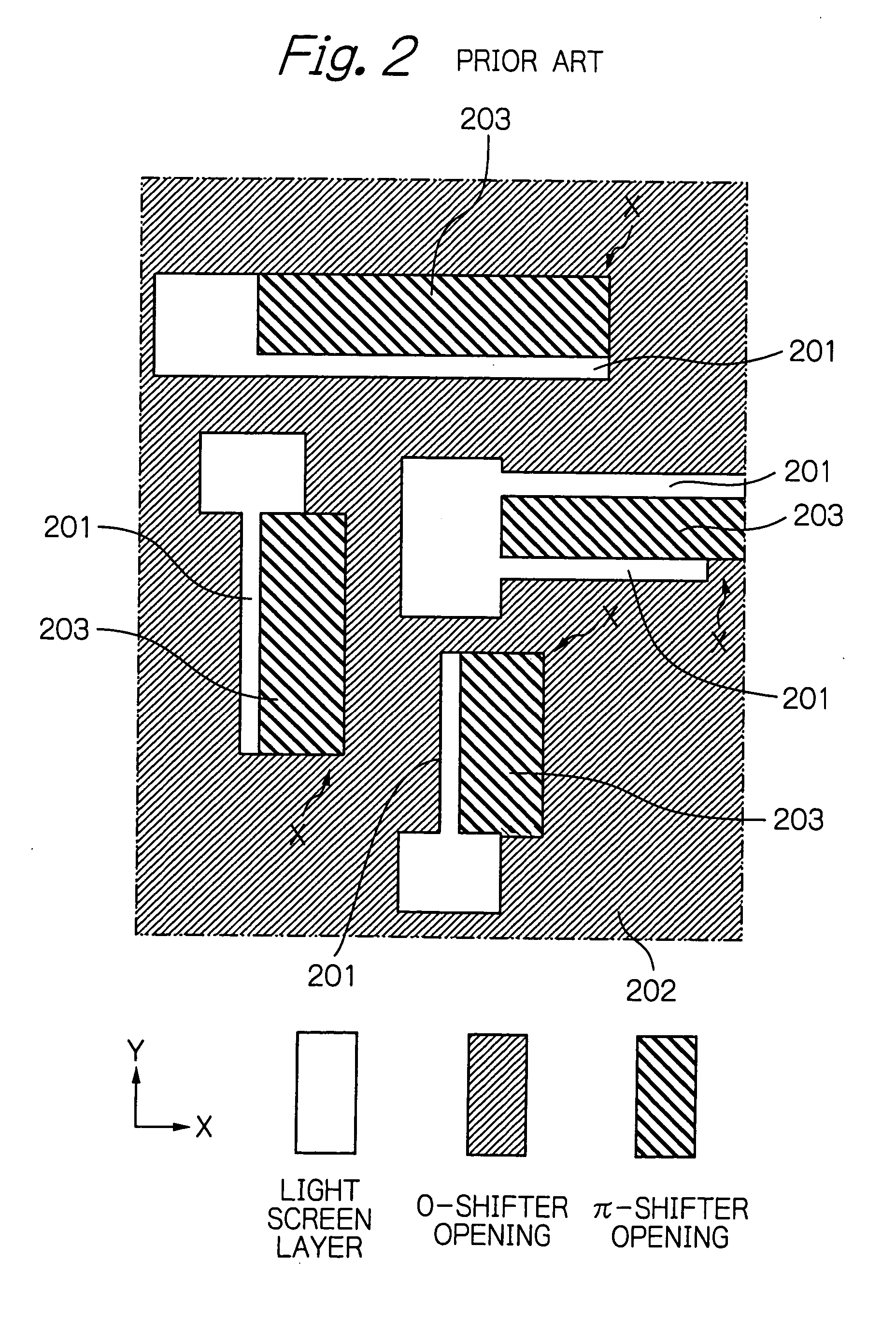
[0050] Before the description of the preferred embodiment, prior art semiconductor device manufacturing methods will be explained with reference to FIGS. 1, 2, 3, 4, 5 and 6.

[0051] In FIG. 1, which is a layout diagram illustrating a semiconductor device, one circuit block (cell) is illustrated. In FIG. 1, gate electrodes 101 are arranged along an X-direction, while gate electrodes 102 are arranged along a Y-direction. Also, in FIG. 1, shaded portions indicate source / drain impurity diffusion regions.

[0052] A phase shift photomask as illustrated in FIG. 2 and a trim photomask as illustrated in FIG. 3 are used to manufacture the gate electrodes 101 and 102 of the semiconductor device of FIG. 1 (see: JP-2003-168640-A).

[0053] In FIG. 2, light screen layers 201 made of Cr or CrO are provided for the gate electrodes 101 and 102 of FIG. 1. Also, O-shifter openings 202 and π-shifter openings 203 surround the light screen layers 201 to generate necessary phase edges below the light screen ...


PUM

PropertyMeasurementUnit
distanceaaaaaaaaaa
distanceaaaaaaaaaa
widthaaaaaaaaaa

Abstract

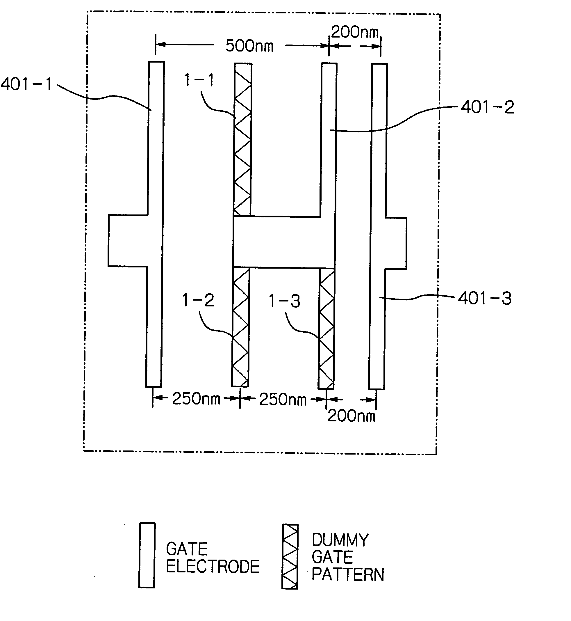
In a method for forming a plurality of gate patterns in parallel with each other on a photoresist layer within one circuit block, at least one dummy gate pattern is formed in parallel with the gate patterns when a pitch between said gate patterns is larger than a predetermined maximum pitch, so that pitches between the gate patterns including the dummy gate pattern are smaller than the predetermined maximum pitch. Then, a photolithography process is performed upon the photoresist layer by using a phase shift photomask having first and second openings whose difference in phase is π. The first and second openings alternate between the gate patterns including the dummy gate pattern to form phase edges therein.

Description

BACKGROUND OF THE INVENTION [0001] 1. Field of the Invention [0002] The present invention relates to a method for forming gate patterns in parallel on a photoresist layer, a method for manufacturing a semiconductor device having gate patterns in parallel, and a phase shift photomask used in such a forming method and such a semiconductor device manufacturing method. [0003] 2. Description of the Related Art [0004] Generally, in semiconductor manufacturing processes, photolithography technology by photomasks has been used. [0005] In the photolithography technology, a resolution limit for defining a dimension of a minimum pattern such as a gate pattern depends upon a wavelength of exposure light. Generally, since it is difficult to form gate patterns having a smaller dimension than a half wavgelength of the exposure light, various high resolution techniques have been developed. One approach is a phase shift photomask such as a Levenson-type phase shift photomask where two transmitted li...

Claims


Application Information

Patent Timeline
Patent Type & Authority Applications(United States)
IPC IPC(8): G03C5/00G03F1/00G03F1/30G03F1/36G03F1/68G03F7/20H01L21/027
CPCG03F1/144G03F1/26G03F1/70
Inventor FUJIMOTO, MASASHI
Owner RENESAS ELECTRONICS CORP
Learn More