Pressure regulating valve for common-rail fuel injection system

a technology of pressure regulation valve and fuel injection system, which is applied in the direction of fluid pressure control, process and machine control, instruments, etc., can solve the problems of assembly cost and laboriousness, and achieve the effect of reducing the length of the valve housing

Inactive Publication Date: 2005-03-17
ROBERT BOSCH GMBH
View PDF2 Cites 0 Cited by
  • Summary
  • Abstract
  • Description
  • Claims
  • Application Information

AI Technical Summary

Benefits of technology

[0016] By means of an external force, which is to be applied to the housing, upsetting can take place at the desired deformation point, and by means of it the longitudinal length of the valve housing is reduced while the air gap between the armature covering and the valve housing is enlarged.

Problems solved by technology

The requisite production tolerances are correspondingly narrow, which means considerable effort and thus expense for assembly.

Method used


Image

  • Pressure regulating valve for common-rail fuel injection system
  • Pressure regulating valve for common-rail fuel injection system

Examples


Embodiment Construction

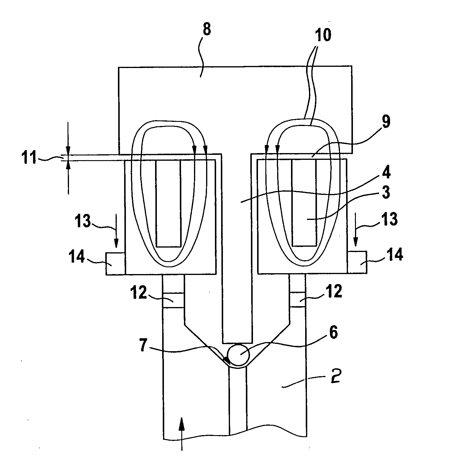
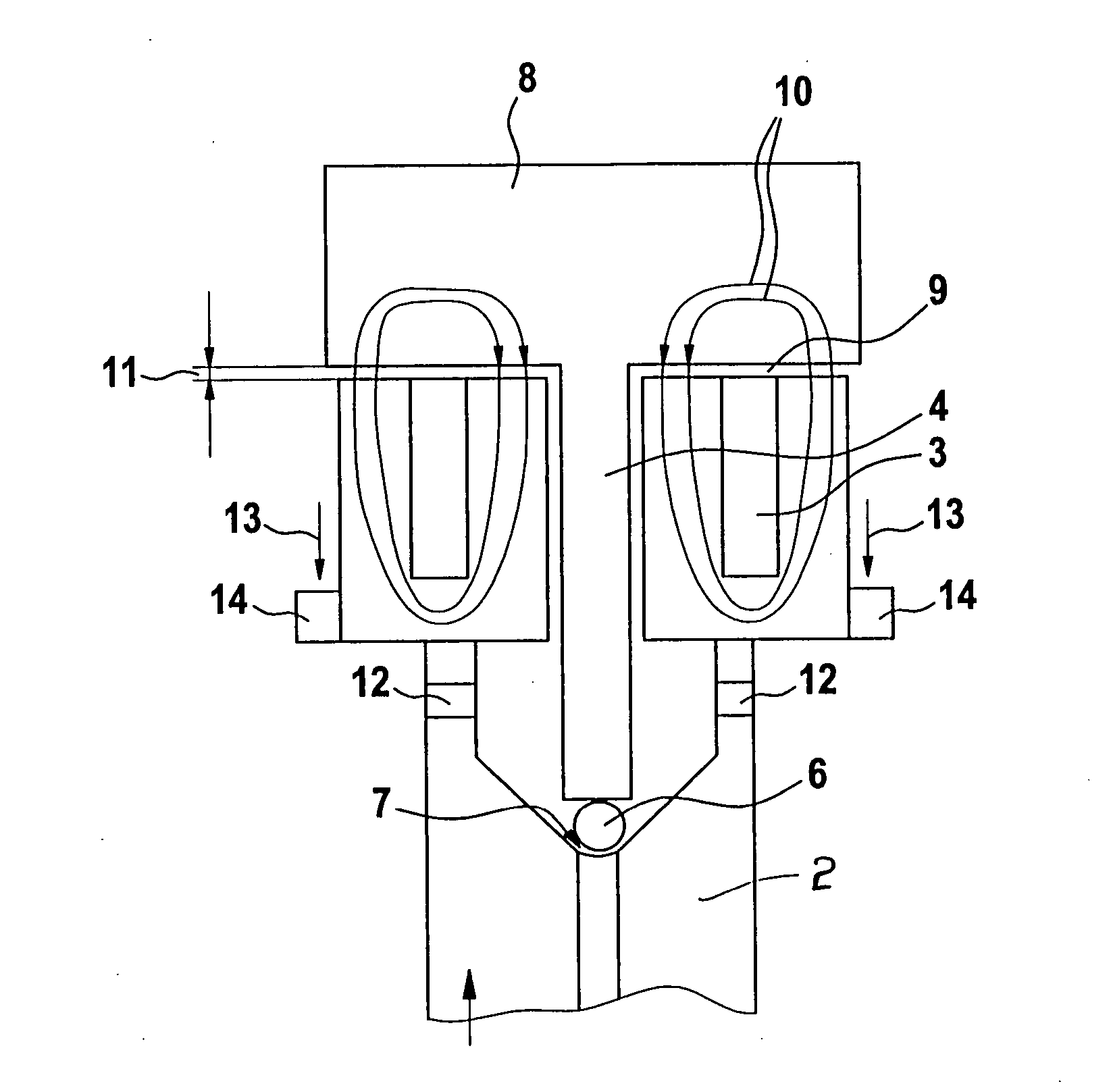
[0020] In FIG. 1, a longitudinal section is shown through a schematic view of a pressure regulating valve 1 which can be disposed on a common rail, not shown in the drawing.

[0021] The pressure regulating valve 1 itself has a valve body 2, in which an electromagnet with a coil winding 3 is disposed. The coil is embedded in soft magnetic material, embodied for instance as transformer sheet metal.

[0022] The armature bolt 4 of the electromagnet 3 is located in an axial recess and can be pressed as a valve member against the closing element 6 and the valve seat 7. The armature furthermore has a covering 8, which is spaced apart from the valve housing 2 by an air gap 9.

[0023] Supplying current to the electromagnet causes the armature covering 8 and armature bolt 4 to be penetrated by magnetic flux lines 10, resulting in a magnetic force which presses the valve member against the closing element 6 and the valve seat 7.

[0024] The magnitude of the force is dependent on the size of the ai...


PUM


Abstract

A pressure regulating valve for regulating the pressure in a common rail, having a pistonlike valve member which is axially displaceably guided in a bore and acts on a closing element that can be pressed against a valve seat, and the valve member forms an armature of an electromagnet, to which current can be supplied. The minimal spacing between the armature and the valve housing is adjustable. In this way, the setting of the closing force of the valve can be done in the preassembled state.

Description

BACKGROUND OF THE INVENTION [0001] 1. Field of the Invention [0002] The invention relates to a pressure regulating valve for a common-rail fuel injection system for internal combustion engines, for regulating the pressure in the common rail and having a pistonlike valve member guided axially displaceably in a bore, which valve member acts on a closing element which can be pressed against a valve seat, and the valve member forms an armature bolt of an electromagnet that can be supplied with current. Electromagnets with movable armatures are furthermore used as actuators in many kinds of applications. [0003] 2. Description of the Prior Art [0004] Pressure regulating valves are known in manifold versions, including pressure regulating valves serving to regulate the pressure in a common rail, with which it communicates via an inlet. The pressure regulating valve has a pistonlike valve member, guided axially displaceably in a bore, that can move counter to a force which is exerted on the...

Claims


Application Information

Patent Timeline
Patent Type & Authority Applications(United States)
IPC IPC(8): F02M55/02F02M37/00F02M59/46F02M63/02F02M69/00F16K31/02G05D16/20
CPCF02M55/025F02M63/0052G05D16/2013F02M63/025F02M63/0225G05D16/2022
Inventor BRAEUER, CHRISTIANHOLL, STEFAN
Owner ROBERT BOSCH GMBH
Why Eureka
Try Eureka