LED filament and LED filament light containing the same

a technology of led filament and led filament light, which is applied in the field of light, can solve the problems of filament bending and deformation repeatedly, affecting service life, and uneven light illumination, and achieves the effects of reducing manufacturing costs, improving light shape, and shortening service li

Active Publication Date: 2017-09-28
SHANDONG PROSPEROUS STAR OPTOELECTRONICS TECH CO LTD
View PDF0 Cites 7 Cited by
  • Summary
  • Abstract
  • Description
  • Claims
  • Application Information

AI Technical Summary

Benefits of technology

[0005]The purpose of the present invention is to provide an LED filament, which can be applied to LED filament light and has characteristics of less solder joint and long service life.
[0011]Another purpose of the present invention is to provide an LED filament light, the light has no blocking component, so that shades and a weak light region are not generated in a light illumination direction, and furthermore, the uniform. three-dimensional light illumination effect is obtained.
[0017]The beneficial effect of the present invention is that LED filaments have free slipping and adjusting function when the lamp filaments are thermally expanded and extended, thereby overcoming the problem of shortened service life due to repeated bending deformation of the LED filaments. Besides, the spot welding connection of one end of the LED filaments and multi-point soldering of a plurality of LED filaments connected in parallel and in series are replaced by permanent magnet attraction connection, thereby simplifying the manufacturing process.
[0018]Particularly, the common spot welding part with non-luminance and light blocking of one end of the LED filament away from the lamp cap is cancelled, and the top end of a conical luminous body also has luminous efficacy, so that shades and a weak light region are prevented from being generated in the lighting direction, so as to obtain an LED filament light with a uniform three-dimensional lighting effect.
[0019]Furtherly, the plurality of LED filaments are extended from a top end of a conical body, so that the filaments are cross distribution, thereby forming an LED filament light with better light shape.

Problems solved by technology

And these power terminals for soldering occupy certain space, so that the light illumination direction generates shadows and weak light region naturally, that is, light illumination is not uniform, and the LED filament light called 360-degree full periphery has obvious defects.
Meanwhile, existing LED filament lights adopt many spot welding technologies, which is complicate.
And after both ends of each filament is rigidly soldered, the LED filament is expanded and contracted repeatedly due to heat at work, so that the filament bends and deforms repeatedly, and the service life is greatly affected.

Method used


Image

  • LED filament and LED filament light containing the same
  • LED filament and LED filament light containing the same
  • LED filament and LED filament light containing the same

Examples


Embodiment Construction

[0031]The present invention is further described in detail in combination with drawings.

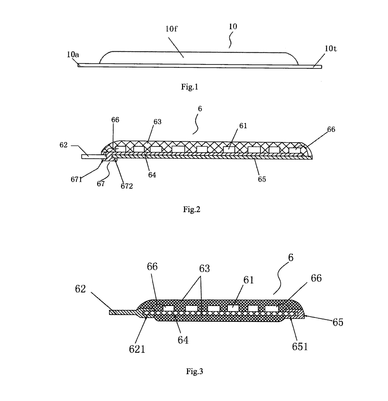
[0032]As shown in FIG. 1, both ends of an LED filament 10 are provided with power terminals 10a and 10t fit dedicated to soldering, which are non-luminous and block the light, and one section encapsulated with a fluorescent glue 10f is a light-emitting section.

[0033]FIG. 2 shows a structure diagram of an embodiment provided by the LED filament. An LED filament 6 comprises a plurality of light-emitting chips 61, a metal electrical terminal 62, a fluorescent glue 63, an insulating substrate 64 and an electrically and magnetically conductive connector 65; the plurality of light-emitting chips 61 are connected in series, and encapsulated and fixed OR a surface of the insulating substrate 64 by the fluorescent glue 63, one face of the electrically and magnetically conductive connector 65 is bonded the other surface of the insulating substrate 64; the metal electrical terminal 62 is electrically connec...


PUM


Abstract

An LED filament, comprising a plurality of light-emitting chips, a metal electrical terminal, a fluorescent glue, an insulating substrate and an electrically and magnetically conductive connector. The plurality of light-emitting chips are connected in series, and encapsulated and fixed on a surface of the insulating substrate by the fluorescent glue, one face of the electrically and magnetically conductive connector is fitted on the other surface of the insulating substrate, the metal electrical terminal is electrically connected to a light-emitting chip at one end of the insulating substrate. Also provided is an LED filament light, comprising a plurality of LED filaments and a permanent magnet. The LED filaments are magnetically and movably connected by means of magnetic attraction via the permanent magnet, and are capable of automatic sliding adjustment during thermal expansion and elongation.

Description

TECHNICAL FIELD[0001]The present invention belongs to light field, and more specifically, to an LED filament and LED filament light.BACKGROUND OF THE PRESENT INVENTION[0002]LED filament light is also called 360-degree full peripheral light in the industry, and is one of ideal energy saving lamps which can replace existing incandescent lamp. The LED filament light is generally made up of a lamp cap connecting the electric supply, an LED power supply installed inside the lamp cap, a glass bulb, a glass stem fixedly in the glass bulb and embedded with a positive wire and a negative wire, and a plurality of LED filaments electrically connected to the positive wire and the negative wire and fixedly on the glass stem. LED filament is emitted via rectification and transformation of the electric supply. LED filament is made by connecting a plurality of light-emitting chips in series, fixing on a thinner substrate and sealing with fluorescent glue. LED filaments with different quantities and...

Claims


Application Information

Patent Timeline
Patent Type & Authority Applications(United States)
IPC IPC(8): F21K9/237F21V23/06F21K9/238F21V3/04F21K9/232F21V23/00F21V17/10F21V3/02
CPCF21K9/237F21V17/101F21V23/06F21V3/02F21Y2115/10F21K9/232F21V23/001F21K9/238F21V17/105F21V3/0418F21K9/90F21V19/005F21Y2103/10F21Y2107/00F21V19/003F21Y2109/00F21V3/061
Inventor LIU, BORENYUAN, XINCHENGKONG, YIPING
Owner SHANDONG PROSPEROUS STAR OPTOELECTRONICS TECH CO LTD
Why Eureka
Try Eureka